Eureka AIR delivers breakthrough ideas for toughest innovation challenges, trusted by R&D personnel around the world.

Natural convection enhanced heat dissipation structure with non-uniform heat source distribution and heat dissipation method thereof

A technology of heat dissipation structure and natural convection, which is applied to the structural parts of electrical equipment, cooling/ventilation/heating renovation, electrical components, etc. Effect

Inactive Publication Date: 2019-08-20
XI AN JIAOTONG UNIV
View PDF7 Cites 2 Cited by
  • Summary
  • Abstract
  • Description
  • Claims
  • Application Information

AI Technical Summary

Problems solved by technology

Fins with a gradual cross-section structure are arranged inside the shell, and tubular air passages with variable cross-sections are formed between the fins. When the heat source contacts the radiator, the heat is conducted to the shell, and the shell exchanges heat with the air to export the heat. The structure cannot effectively dissipate heat from devices with high-power heat sources in local areas, and the manufacturing and processing costs of fins with variable cross-section structures are high

Method used


Image

  • Natural convection enhanced heat dissipation structure with non-uniform heat source distribution and heat dissipation method thereof
  • Natural convection enhanced heat dissipation structure with non-uniform heat source distribution and heat dissipation method thereof
  • Natural convection enhanced heat dissipation structure with non-uniform heat source distribution and heat dissipation method thereof

Examples


Embodiment Construction

[0030] Below in conjunction with accompanying drawing and specific embodiment the present invention is described in further detail:

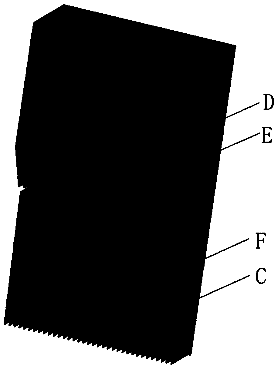
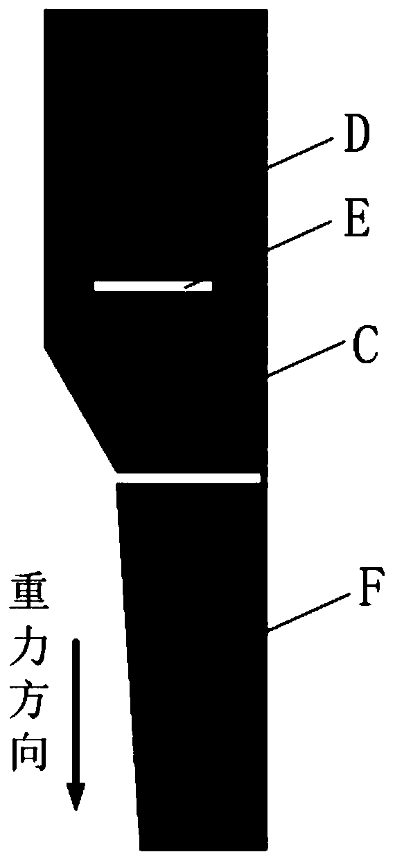
[0031] Such as figure 1 , figure 2 with image 3 As shown, the present invention has a natural convection enhanced heat dissipation structure with non-uniform heat source distribution, including a heat dissipation thin substrate C (the heat dissipation thin substrate C is a lightweight thin aluminum substrate, which is the most basic component of the entire heat dissipation structure, and all other components are related to it. connected), placed on the upper part of the heat dissipation thin substrate C with a flowering tooth D with ventilation holes E, placed on the inclined tooth F on the lower part of the heat dissipation thin substrate C, and on the back of the heat dissipation thin substrate C is provided with a low-power heat source S0, the heat dissipation thin There are multiple high-power heat sources distributed on the back of the ...


PUM

PropertyMeasurementUnit
Thicknessaaaaaaaaaa

Abstract

The invention relates to a natural convection enhanced heat dissipation structure with non-uniform heat source distribution and a heat dissipation method thereof. The structure comprises a heat dissipation thin substrate, spline teeth with vent holes arranged at the upper portion of the front surface of the heat dissipation thin substrate, inclination teeth arranged at the lower portion of the front surface of the heat dissipation thin substrate, low-power heat sources uniformly distributed at the back surface of the heat dissipation thin substrate, and a plurality of high-power heat sources distributed at the back surface of the heat dissipation thin substrate. A VC (Vapor Chamber) is inlaid in the heat dissipation thin substrate in the high-power heat source distribution dense area and an anisotropic graphene sheet is inlaid in the heat dissipation thin substrate in the high-power heat source sparse area; the VC and the anisotropic graphene sheet have good power flattening effect toeffectively reduce the local temperature at the high-power heat sources, the whole radiator is forming by processing light aluminum so that the weight is light, the heat conducting performance is good, the staggered tooth and broken tooth structures of the spline teeth and the inclination teeth are beneficial to strengthening heat dissipation, and the radiator is simple in structure, convenient toprocess and high in reliability.

Description

technical field [0001] The invention belongs to the technical field of natural heat dissipation, and is mainly aimed at outdoor electronic equipment relying on air natural convection for heat dissipation, and in particular relates to a natural convection enhanced heat dissipation structure and heat dissipation method with non-uniform heat source distribution. Background technique [0002] Natural convection refers to the heat transfer phenomenon in which the fluid moves only by the buoyant force generated by the density difference caused by the temperature difference inside the fluid without external forced drive. The natural convection heat dissipation method is one of the most common heat dissipation methods, which has many excellent characteristics such as simple structure, high reliability, low cost, and convenient maintenance. [0003] For outdoor electronic equipment, natural convection heat dissipation is the most commonly used heat dissipation method. As the power of...

Claims


Application Information

Patent Timeline
IPC IPC(8): H05K7/20
CPCH05K7/20127
Inventor 张大林周健成孙汝雷宋功乐田文喜秋穗正苏光辉
Owner XI AN JIAOTONG UNIV
Why Eureka
Eureka Blog
Learn More