
Method for designing low-stray inductance loop of high-frequency inverter

A high-frequency inverter, stray inductance technology, applied in the direction of conversion equipment structural parts, electrical components, AC power input to DC power output, etc., can solve the problem of large current change rate, fast switching speed, and voltage overshoot. and other problems to achieve the effect of suppressing voltage overshoot and electromagnetic interference

Active Publication Date: 2019-08-20
BEIJING JIAOTONG UNIV +1
View PDF3 Cites 4 Cited by
  • Summary
  • Abstract
  • Description
  • Claims
  • Application Information

AI Technical Summary

Problems solved by technology

In the high-frequency inverter, the switching speed is fast and the current change rate is large. The current change rate and the loop inductance will cause voltage overshoot, which will affect the normal use of power devices.

Method used


Image

  • Method for designing low-stray inductance loop of high-frequency inverter
  • Method for designing low-stray inductance loop of high-frequency inverter
  • Method for designing low-stray inductance loop of high-frequency inverter

Examples


Embodiment Construction

[0049] In order to make the objectives, technical solutions and advantages of the present invention clearer, the following further describes the present invention in detail with reference to the accompanying drawings and embodiments. It should be understood that the specific embodiments described here are only used to explain the present invention, but not to limit the present invention.

[0050] On the contrary, the present invention covers any alternatives, modifications, equivalent methods and schemes defined by the claims that make the essence and scope of the present invention. Further, in order to enable the public to have a better understanding of the present invention, in the following detailed description of the present invention, some specific details are described in detail. Those skilled in the art can fully understand the present invention without the description of these details.

[0051] The present invention provides an embodiment of a method for designing a low st...


PUM


Abstract

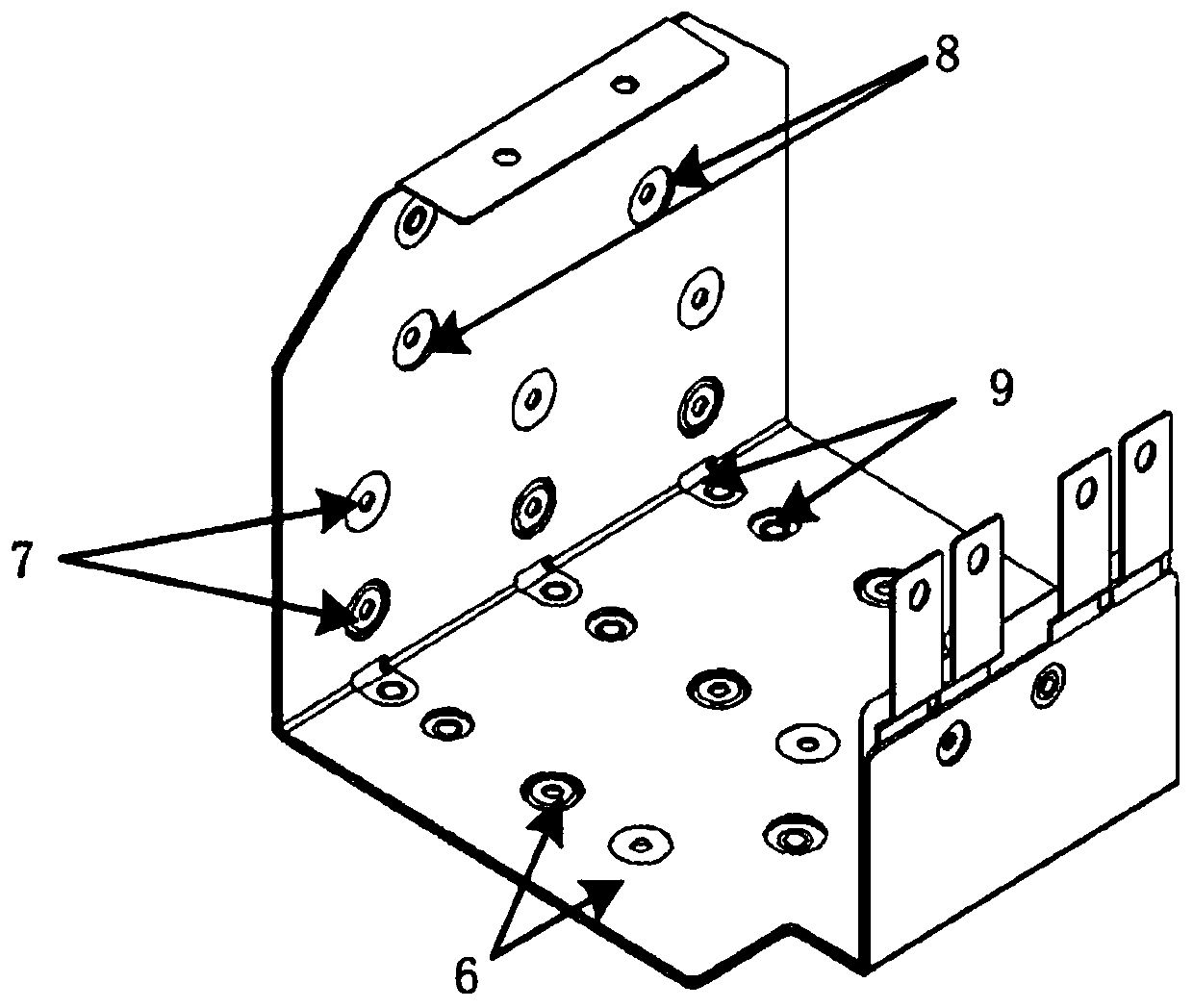
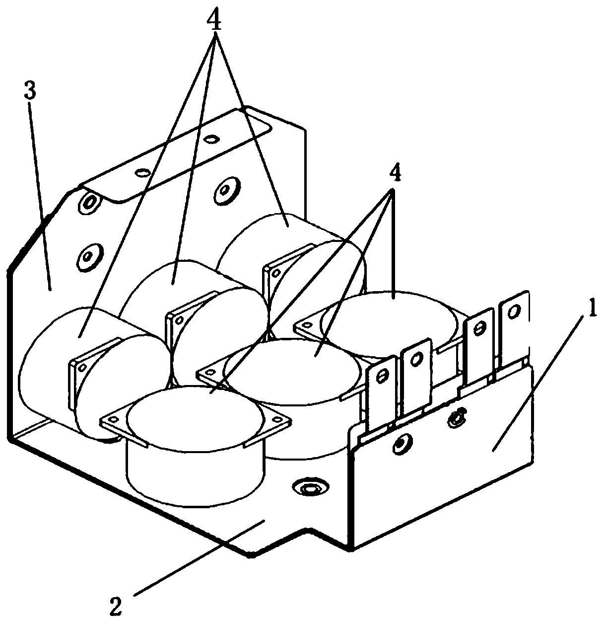
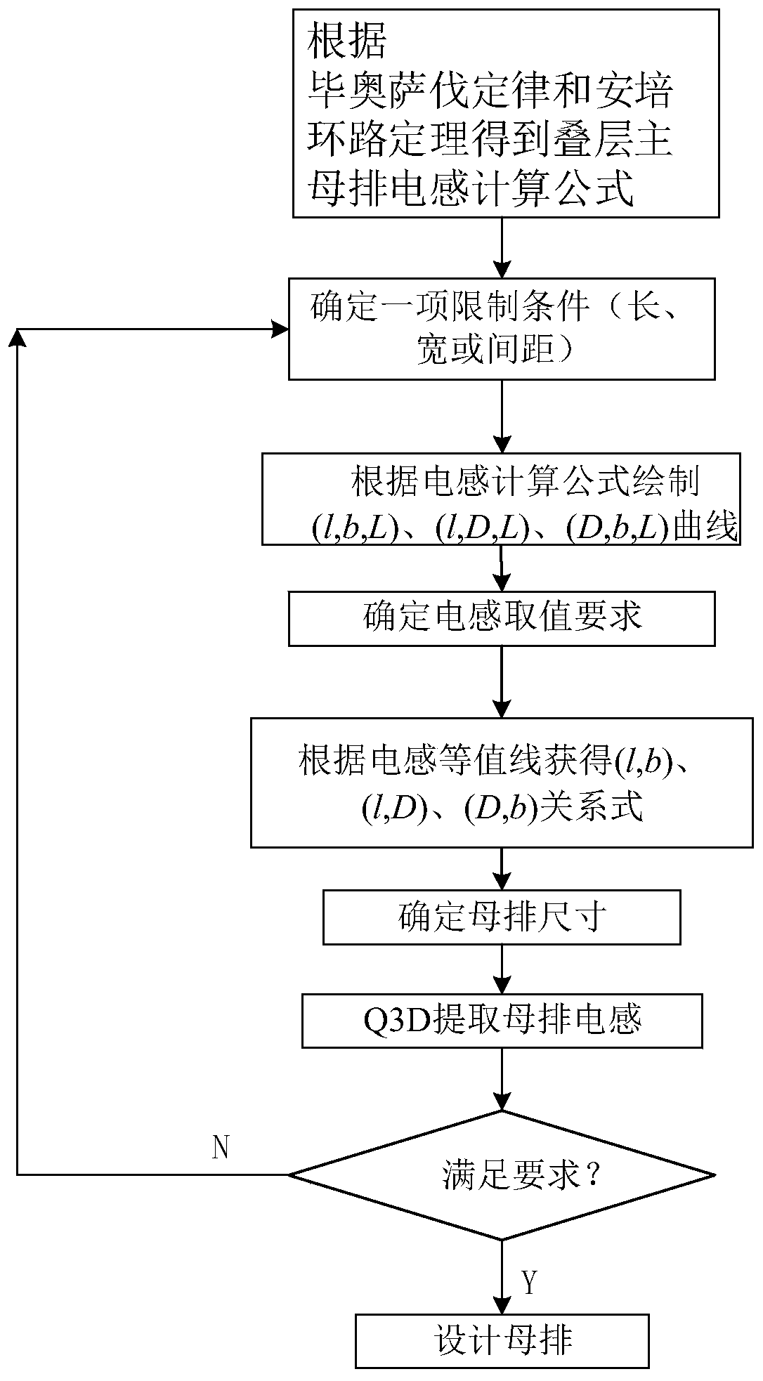
The invention belongs to the technical field of high-frequency inverters, and particularly relates to a method for designing a low-stray inductance loop of a high-frequency inverter. A main busbar ofa converter loop is of a laminated structure and comprises two layers cooper bars including positive copper bars and negative copper bars, and the width, the length and the thickness of the positive copper bars and the negative copper bars are the same. The size specification of the main busbar under the expected inductance value is determined according to the width and length of the copper bars in the main busbar and the influence of the distance between the two layers of copper bars on the stray inductance of the main busbar. An absorption capacitor module is arranged on the main busbar andis used for inhibiting voltage spike caused by busbar inductance and reducing loop equivalent inductance. The absorption capacitor module comprises a plurality of small capacitors arranged in parallel, and the capacitance values of the small capacitors in the absorption capacitor module are determined through an equivalent circuit of the double-pulse test circuit. Based on the joint simulation ofQ3D and simplorer, the number of small capacitors in an absorption capacitor module is changed or the size specification of a main busbar is changed, so that a power loop conforming to the expected value of the final inductance is obtained.

Description

Technical field [0001] The invention belongs to the technical field of high-frequency inverters, and specifically relates to a method for designing a low stray inductance loop of a high-frequency inverter. Background technique [0002] Inverters are widely used in many fields such as communication, transportation and electric power, and are developing towards high frequency, high efficiency and small size. As inverters increase their requirements for volume and efficiency, their operating frequency must continue to increase. Faster switching speeds make the switching devices more sensitive to stray inductance, which can easily cause serious problems during the switching process, such as voltage stress, electromagnetic interference, and additional power loss. Therefore, high-frequency inverters have more stringent requirements for loop stray parameters. Especially in high-power inverters, in order to eliminate the voltage overshoot caused by stray inductance, the stray parameters...

Claims


Application Information

Patent Timeline
Patent Type & Authority Applications(China)
IPC IPC(8): H02M7/00H02M1/44H02M1/32
CPCH02M1/32H02M1/44H02M7/003
Inventor 刁利军刘博李伟杰顾诚博刁利坚梅伟耀张艳
Owner BEIJING JIAOTONG UNIV
Learn More