Eureka AIR delivers breakthrough ideas for toughest innovation challenges, trusted by R&D personnel around the world.

Self-diagnosis method and system for numerical control machine

A technology of self-diagnosis system and CNC machine tool, which is applied in general control system, control/adjustment system, program control, etc. It can solve the problem that the specific cause of product failure cannot be obtained, and achieve the effect of convenient maintenance and improved detection efficiency

Active Publication Date: 2019-08-16
苏州金利宝电子科技有限公司
View PDF5 Cites 2 Cited by
  • Summary
  • Abstract
  • Description
  • Claims
  • Application Information

AI Technical Summary

Problems solved by technology

[0004] Although this diagnostic method can determine whether the processed product meets the processing requirements, it cannot find out the specific reasons for the product's problems, and needs to be improved.

Method used


Image

  • Self-diagnosis method and system for numerical control machine
  • Self-diagnosis method and system for numerical control machine

Examples


Embodiment 1

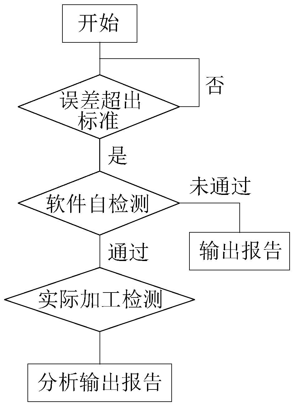
[0040] A kind of numerical control machine tool self-diagnosis method, refer to figure 1 , including step S101 to step S102.

[0041] Step S101: When the error exceeds the standard, first run the software self-test, including the system simulation operation with the same process and parameters, test whether the total error meets the standard, and decompose the processing process, and simulate each step through the system to test whether the error of the step meets the standard. standard.

[0042] The error in step S101 exceeds the standard, which refers to the error compared with the standard size after the workpiece is processed. For the specific detection of the workpiece, refer to the invention patent with application number 201410605568.6. Software self-inspection means that the controller of the lathe runs the simulation inspection software, and runs the program simulation processing with the same parameters and the same process without load. Finally, compare the total ...

Embodiment 2

[0049] A self-diagnosis system for CNC machine tools, referring to figure 2 , including a processor 1 and a memory 2, the memory 2 stores an instruction set for the processor 1 to call to realize the following functions:

[0050] When the error exceeds the standard, first run the software self-test, including the system simulation operation with the same process and parameters, test whether the total error meets the standard, and decompose the processing process, and simulate each step through the system to test whether the error of the step meets the standard;

[0051] After the software self-inspection is passed, the actual processing inspection is carried out, including the actual processing with the same process and parameters, and the error after each processing step is detected during the processing process, and compared with the standard error of each step, and decomposed The two processing steps before and after are processed separately, and the total error of detecti...


PUM


Abstract

The present invention discloses a self-diagnosis method and system for a numerical control machine, and relates to machine tool processing. When an error exceeds a standard, software is run for self-detection, which includes that system simulation operation is performed with the same process and parameters to test whether a total error meets the standard, and a machining flow is decomposed to testwhether a step error meets the standard through each step of the system simulation; and after the self-detection of the software passes, actual machining detection is performed, which includes that the actual machining is performed with the same process and parameters, the error after the completion of each machining step is detected in the machining process and compared with the standard error of each step, the two successive machining steps are decomposed for respective machining, and the total error is detected and compared with the standard error of the machining process. The software isfirst detected to determine the specific steps in which the error occurs. After the self-detection of the software, the actual machining detection is performed so that the detection efficiency is improved. The whole solution can intuitively determine the specific steps in which the error occurs, and maintenance is convenient.

Description

technical field [0001] The invention relates to lathe processing, more specifically, it relates to a method and system for self-diagnosis of a numerically controlled machine tool. Background technique [0002] CNC machine tool is the abbreviation of numerical control machine tool, which is an automatic machine tool equipped with a program control system. The control system can logically process programs with control codes or other symbolic instructions, decode them, express them in coded numbers, and input them into the numerical control device through the information carrier. After calculation and processing, various control signals are sent by the numerical control device to control the movement of the machine tool, and the parts are automatically processed according to the shape and size required by the drawing. [0003] At present, the Chinese patent with application number 201410605568.6 discloses a method for self-diagnosing the processing status of products used in C...

Claims


Application Information

Patent Timeline
Patent Type & Authority Applications(China)
IPC IPC(8): G05B19/406
CPCG05B19/406Y02P90/02
Inventor 李勇
Owner 苏州金利宝电子科技有限公司
Why Eureka
Eureka Blog
Learn More