Bubbling pipe with functions of reverse flow prevention and flow dividing for desulfurizing tower

The technology of bubbling tube and desulfurization tower is applied in the field of renewable clean energy, which can solve the problems of clogging of bubbling tube by limestone solution, uneven distribution and high sulfur content of exhaust gas, so as to avoid the reduction of desulfurization effect, ensure desulfurization effect, Good desulfurization effect

Active Publication Date: 2019-08-13
宁夏峰业环保科技有限公司
View PDF9 Cites 0 Cited by
  • Summary
  • Abstract
  • Description
  • Claims
  • Application Information

AI Technical Summary

Problems solved by technology

[0005] 1. When the exhaust gas passes through the bubbling tube, the air flow is relatively turbulent and the distribution is uneven, which makes it difficult to completely react the remaining 42% of sulfur oxide when the exhaust gas is in contact with the limestone solution, resulting in an excessively high sulfur content in the exhaust gas;
[0006] 2. The exhaust gas itself has temperature. Since the bottom of the bubbling tube is immersed in the limestone solution, when the desulfurization tower stops working and the temperature in the tube drops, the solution will easily flow back, causing the bubbling tube to be blocked by the limestone solution, which will affect the next time. use

Method used


Image

  • Bubbling pipe with functions of reverse flow prevention and flow dividing for desulfurizing tower
  • Bubbling pipe with functions of reverse flow prevention and flow dividing for desulfurizing tower
  • Bubbling pipe with functions of reverse flow prevention and flow dividing for desulfurizing tower

Examples


Embodiment Construction

[0025] The following will clearly and completely describe the technical solutions in the embodiments of the present invention with reference to the accompanying drawings in the embodiments of the present invention. Obviously, the described embodiments are only some, not all, embodiments of the present invention. Based on the embodiments of the present invention, all other embodiments obtained by persons of ordinary skill in the art without making creative efforts belong to the protection scope of the present invention.

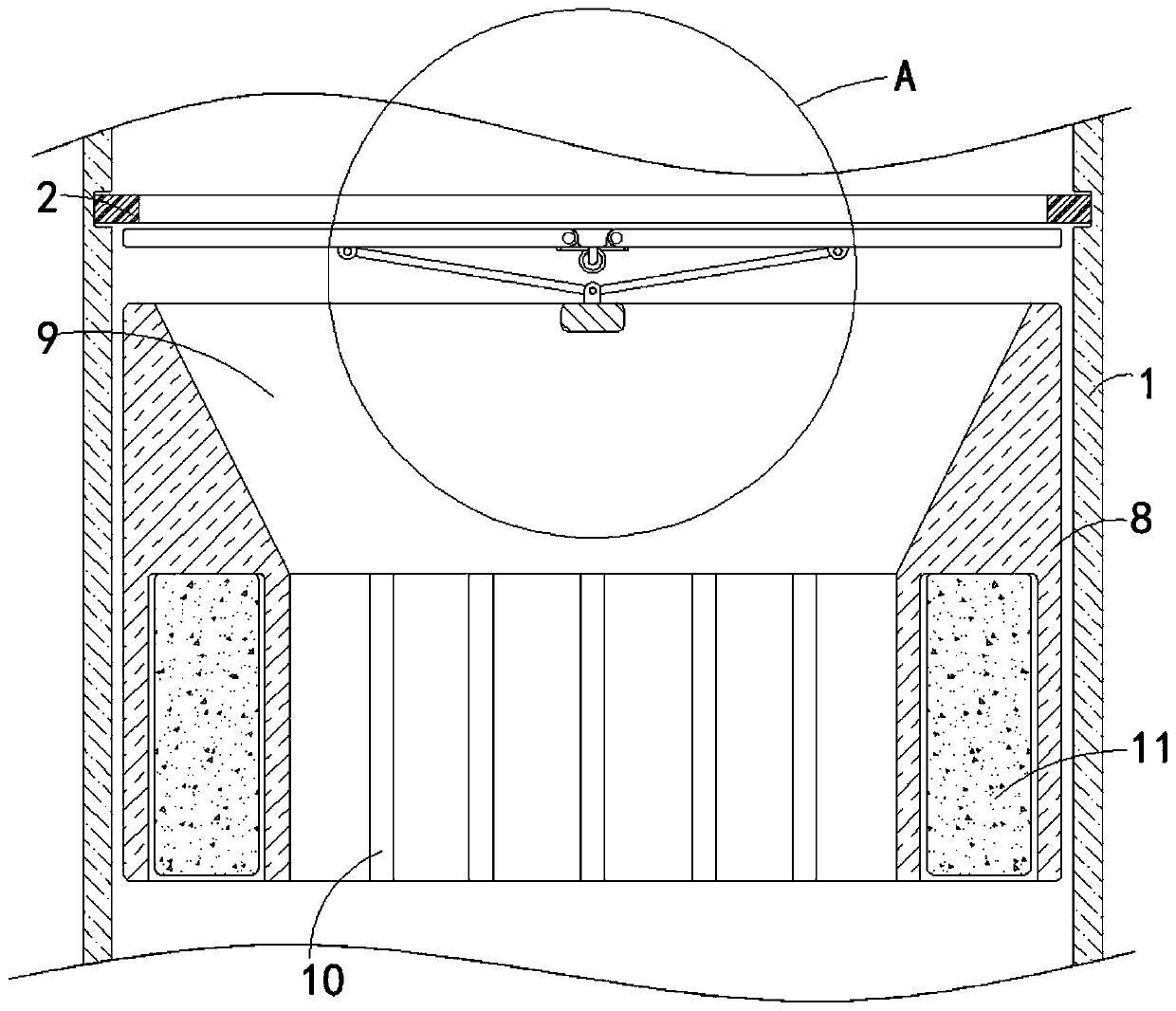
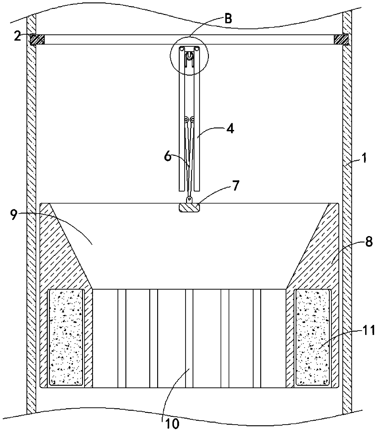
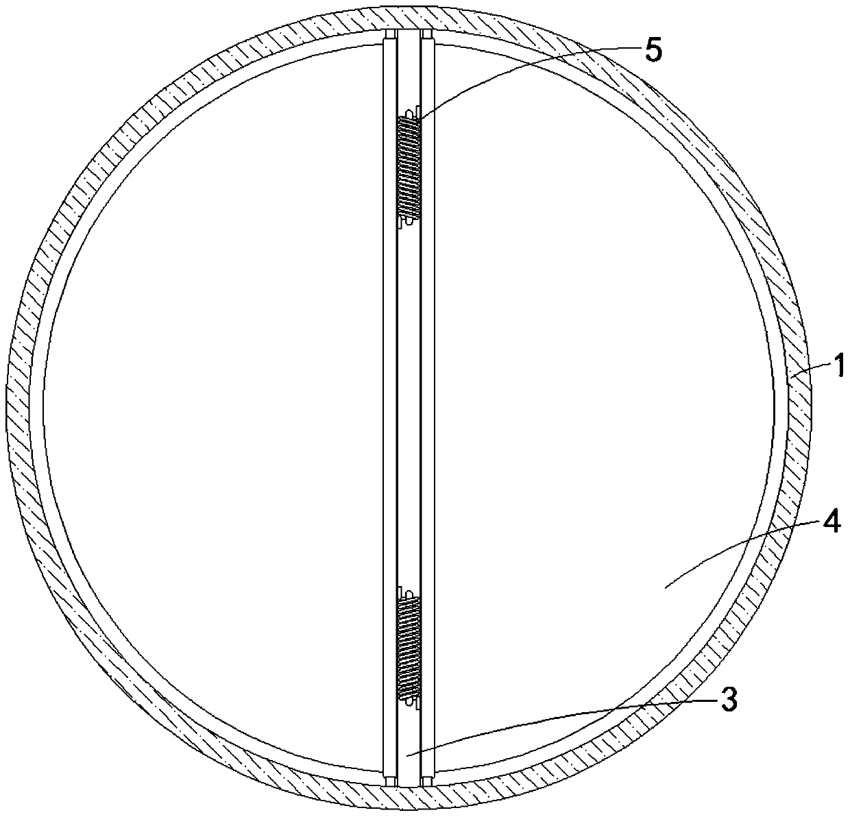
[0026] see Figure 1-8 , a anti-backflow and split flow desulfurization tower bubble tube, comprising a bubble tube 1, the material of the bubble tube 1 is steel material and the inner diameter of the bubble tube 1 is equal to the outer diameter of the movable tube 8, the sealing ring 2 The outer diameter is larger than the inner diameter of the bubbler tube 1 and the inner diameter of the sealing ring 3 is smaller than the diameter of the movable valve 4. The...


PUM


Abstract

The invention discloses a bubbling pipe with functions of reverse flow prevention and flow dividing for a desulfurizing tower, and relates to the technical field of renewable clean energy. The bubbling pipe comprises a bubbling pipe body, a sealing ring is fixedly connected to the inner side of the top of the bubbling pipe body, and a fixation block is fixedly connected to the portion, close to the bottom of the sealing ring, of the inner side of the bubbling pipe body. According to the bubbling pipe with the functions of reverse flow prevention and flow dividing for the desulfurizing tower, floating blocks and movable valves are used cooperatively, when waste gas to be subjected to a reaction is introduced into the bubbling pipe body, the movable valves are opened under blowing of the waste gas and the function of gravity of a movable pipe, after the desulfurizing tower stops work, the temperature in the bubbling pipe body can be lowered, a limestone solution easily flows back into the bubbling pipe body, and the movable pipe can float upwards under the effect of buoyancy of the floating blocks since the density of the floating blocks at the bottom of the movable pipe is smaller than that of the limestone solution; moreover, the movable pipe can make the movable valves closed through hinging rods, the limestone solution is prevented from entering the middle layer of the desulfurizing tower from the bubbling pipe body, the situation that the desulfurizing efficiency is lowered due to backflow is avoided, and the desulfurizing effect is guaranteed accordingly.

Description

technical field [0001] The invention relates to the technical field of renewable clean energy, in particular to a bubbling tube for a desulfurization tower with anti-backflow and split flow. Background technique [0002] Air pollution has become a global problem. Air pollution is mainly caused by sulfides, nitrides, and carbides in industrial production and daily life. The production of these harmful substances accelerates air pollution and causes serious damage to the atmosphere. In order to control To further pollute the atmosphere, the government ordered to strictly control the emission indicators of large-scale industrial production waste gas. The current factory uses a series of desulfurization and denitrification equipment to treat the sulfide in the waste gas. [0003] The desulfurization device in the industry is a desulfurization tower. The current working principle of the desulfurization tower is to pass the exhaust gas into the middle of the desulfurization tower,...

Claims


Application Information

Patent Timeline
Patent Type & Authority Applications(China)
IPC IPC(8): B01D53/50B01D53/78
CPCB01D53/504B01D53/78B01D2251/404B01D2251/606
Inventor 李哲
Owner 宁夏峰业环保科技有限公司
Why Eureka
Try Eureka