
Chip package module and circuit board structure comprising the same

A chip packaging and circuit board technology, applied in the direction of circuit, printed circuit, printed circuit manufacturing, etc., to achieve the effect of volume reduction, high conductivity, and volume reduction

Inactive Publication Date: 2019-08-09
IND TECH RES INST
View PDF6 Cites 2 Cited by
  • Summary
  • Abstract
  • Description
  • Claims
  • Application Information

AI Technical Summary

Problems solved by technology

Although this method can improve the electrical conductivity and thermal conductivity of the package structure, however, when a large current passes through the solder material, the solder material that is not resistant to high current will produce hole-like defects in the material structure, resulting in long-term damage to the product. After use or during the reliability test, the open circuit between the upper and lower components connected by the solder material

Method used


Image

  • Chip package module and circuit board structure comprising the same
  • Chip package module and circuit board structure comprising the same
  • Chip package module and circuit board structure comprising the same

Examples


Embodiment Construction

[0042] The foregoing and other technical contents related to the embodiments of the present invention will be clearly presented in the following detailed description of the embodiments with reference to the accompanying drawings. The directional terms mentioned in the following embodiments, such as "upper", "lower", "front", "rear", "left", "right", etc., are only referring to the directions of the accompanying drawings. Accordingly, the directional terms used are illustrative, not limiting, of the invention. Also, in the following embodiments, the same or similar components will be given the same or similar symbols.

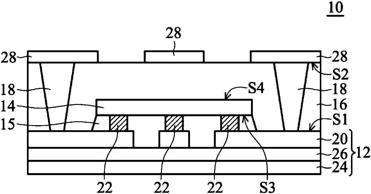
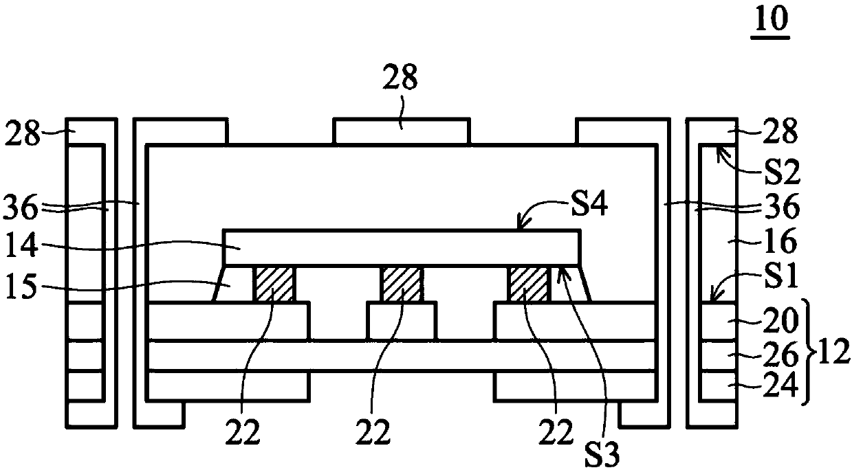
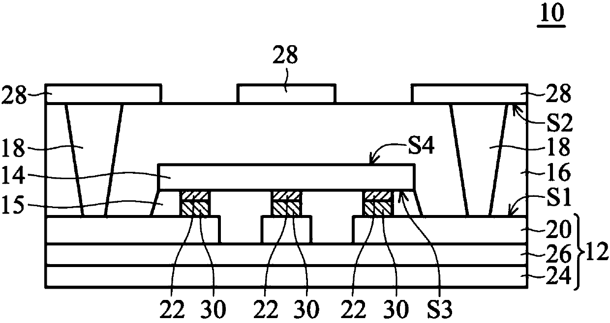
[0043] Figure 1 to Figure 4 It is a schematic cross-sectional view of a chip package module according to the first embodiment of the present invention.

[0044] Please refer to figure 1 , in this embodiment, the chip packaging module 10 includes a molding layer 16 , a chip 14 and a substrate 12 . The molding layer 16 has a first surface S1 and a second surf...


PUM


Abstract

The invention provides a chip package module and a circuit board structure comprising the same. The chip package module includes an encapsulation layer, a chip, a substrate and a plurality of blind-hole electrodes. The encapsulation layer includes a first surface and a second surface opposite to the first surface. The chip includes a third surface and a fourth surface opposite to the third surface. A metal bump is fabricated on the third surface of the chip. The chip is embedded into the encapsulation layer from the first surface of the encapsulation layer. The metal bump is exposed from the first surface of the encapsulation layer. The substrate includes a metal layer, wherein the metal layer of the substrate is bonded to the chip through the metal bump. The plurality of blind-hole electrodes pass through the second surface of the encapsulation layer and are electrically connected to the metal layer of the substrate.

Description

technical field [0001] The invention relates to a chip packaging module and a circuit board structure containing the chip packaging module. Background technique [0002] In the packaging structure of general power semiconductors, the power chip is first assembled on the lead frame through solder material, and then wire bonding is performed. However, this wire bonding method does not help the heat dissipation of the components, and the reliability is not good. At present, some operators assemble the power chip onto the substrate in a flip-chip manner through solder material. Although this method can improve the electrical conductivity and thermal conductivity of the package structure, however, when a large current passes through the solder material, the solder material that is not resistant to high current will produce hole-like defects in the material structure, resulting in long-term damage to the product. After use or during the reliability test, the open circuit between...

Claims


Application Information

Patent Timeline
Patent Type & Authority Applications(China)
IPC IPC(8): H01L23/31H01L23/367H01L23/488
CPCH01L23/3114H01L23/367H01L24/10H01L23/488H01L23/3121H01L23/13H01L23/5389H01L23/5384H01L23/3107H01L23/3135H01L23/315H01L23/3157H01L23/481H01L23/5226H01L2224/73204H01L2224/92125H01L2224/16227H01L2224/32225H01L2224/81191H01L2224/81193H01L2224/73265H01L2224/48227H01L2224/48091H01L2924/15313H01L2924/15159H01L2924/19105H01L24/81H01L24/13H01L24/48H01L24/32H01L24/73H01L24/92H01L2224/73259H01L2224/92224H01L2924/1532H01L2225/1023H01L2225/1094H01L2224/04105H05K3/4694H05K1/185H01L2224/13139H01L2224/13157H01L2224/13147H01L2224/81424H01L2224/13166H01L2224/13144H01L2224/81447H01L2224/13109H01L2224/2919H01L2224/131H01L2224/13164H01L2224/13149H01L2924/00012H01L2924/00014H01L2224/16225H01L2924/00H01L2924/013H01L2924/014H01L24/16H01L2924/1811H01L2924/18161H01L2924/1815H01L2924/1515H01L2924/1517H01L24/25
Inventor 黄馨仪林育民张道智
Owner IND TECH RES INST
Learn More