
Method for carrying out half-in-site observation on initiation position of point corrosion pit

An in-situ, pitting corrosion technology, applied in the field of austenitic-ferritic duplex stainless steel, can solve the problems of unclear G-phase and α effects, inability to determine the location of nano-scale pitting pit initiation, etc. high degree of effect

Active Publication Date: 2019-08-09
UNIV OF SCI & TECH BEIJING
View PDF3 Cites 3 Cited by
  • Summary
  • Abstract
  • Description
  • Claims
  • Application Information

AI Technical Summary

Problems solved by technology

With the help of chemical immersion and electrochemical testing methods, only the position and shape of the pitting pits after they grow up can be obtained, and the size is in the micron order, and the position of the initiation of nano-scale pitting pits cannot be determined.
At the same time, the effect of G phase and α relative pitting performance is not clear

Method used


Image

  • Method for carrying out half-in-site observation on initiation position of point corrosion pit
  • Method for carrying out half-in-site observation on initiation position of point corrosion pit
  • Method for carrying out half-in-site observation on initiation position of point corrosion pit

Examples


Embodiment 1

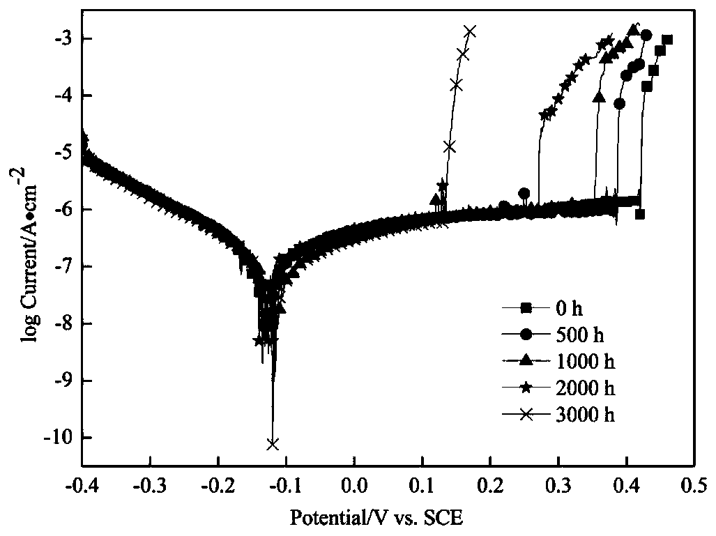
[0031] The Z3CN20.09M stainless steel heat-aged at 475°C for 2000 hours was cut into 15mm×15mm×5mm specimens, which were ground and polished. Put in 6wt.% FeCl at 35°C 3 After soaking in acid solution for 24 hours, the samples were taken out and subjected to ultrasonic pickling treatment immediately, and the corrosion morphology was observed under a metallographic microscope. It can be seen that the location of corrosion is mainly concentrated in the ferrite.

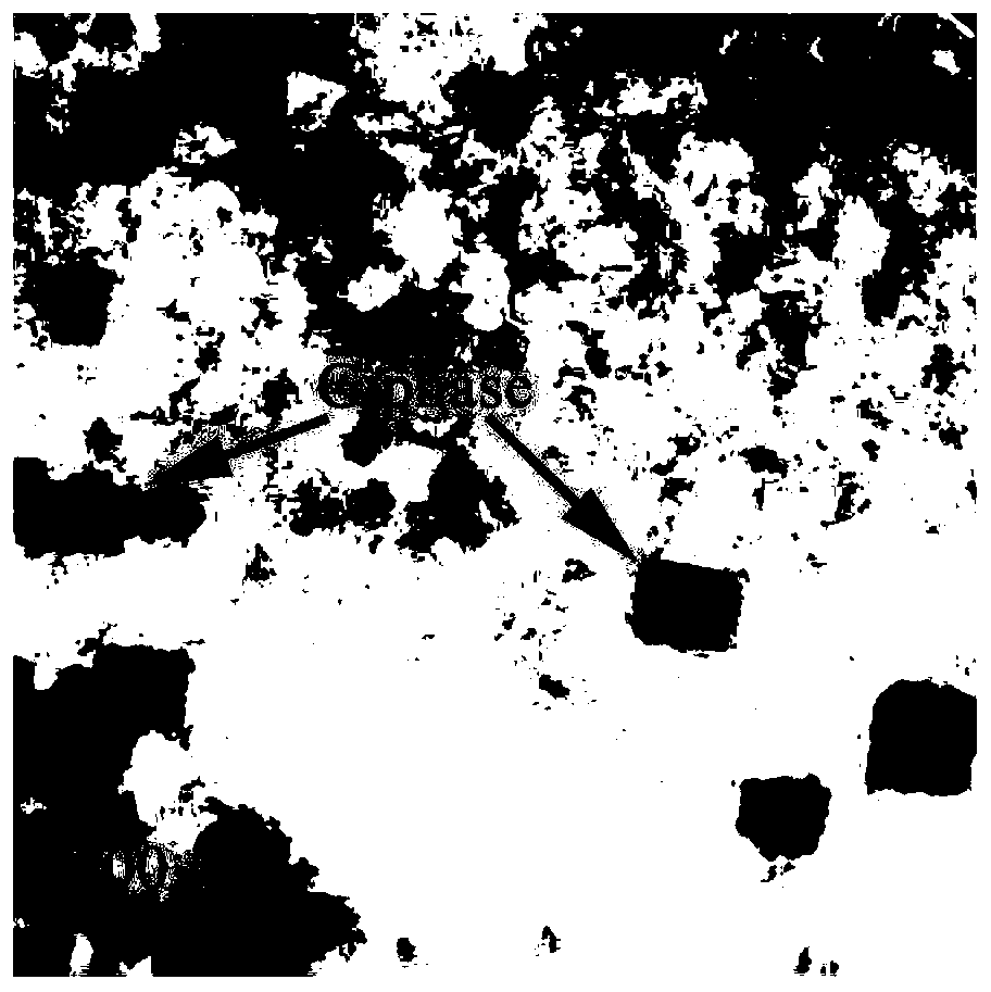
[0032] Cut the Z3CN20.09M stainless steel sample heat-aged at 475°C for 2000 hours into 0.5mm thick slices, grind it with 600#, 1200#, 2000# metallographic sandpaper in turn to 60-100μm and punch into a 3mm diameter disc. Then use 2000# metallographic sandpaper to polish to below 50μm thickness. The polished sample was initially thinned in an electrolytic double-spray apparatus, and the electrolyte was 95% ethanol + 5% perchloric acid, and then the ion thinning apparatus was used to finally thin it into a transmission...

Embodiment 2

[0038] The Z3CN20.09M stainless steel heat-aged at 475°C for 2000 hours was cut into 15mm×15mm×5mm specimens, which were ground and polished. Put in 6wt.% FeCl at 35°C 3 After soaking in acid solution for 24 hours, the samples were taken out and subjected to ultrasonic pickling treatment immediately, and the corrosion morphology was observed under a metallographic microscope. It can be seen that the location of corrosion is mainly concentrated in the ferrite.

[0039] Cut the Z3CN20.09M stainless steel sample heat-aged at 475°C for 2000 hours into 0.5mm thick slices, grind them to 60-100μm with 600#, 1200#, and 2000# metallographic sandpaper in turn, and punch them into discs with a diameter of 3mm. Then use 2000# metallographic sandpaper to polish to below 50μm thickness. The polished sample was initially thinned in an electrolytic double-spray apparatus, and the electrolyte was 95% ethanol + 5% perchloric acid, and then the ion thinning apparatus was used to finally thin i...

Embodiment 3

[0045]The Z3CN20.09M stainless steel heat-aged at 475°C for 3000 hours was cut into 15mm×15mm×5mm specimens, which were ground and polished. Put in 6wt.% FeCl at 35°C 3 After soaking in acid solution for 24 hours, the samples were taken out and subjected to ultrasonic pickling treatment immediately, and the corrosion morphology was observed under a metallographic microscope. It can be seen that the location of corrosion is mainly concentrated in the ferrite.

[0046] The Z3CN20.09M stainless steel sample that was heat-aged at 475°C for 3000 hours was cut into 0.5mm thick slices, polished with 600#, 1200#, 2000# metallographic sandpaper to 60-100μm in turn and punched into a 3mm diameter disc. Then use 2000# metallographic sandpaper to polish to below 50μm thickness. The polished sample was initially thinned in an electrolytic double-spray apparatus, and the electrolyte was 95% ethanol + 5% perchloric acid, and then the ion thinning apparatus was used to finally thin it into ...


PUM


Abstract

The invention relates to a method for carrying out half-in-site observation on an initiation position of a point corrosion pit, and belongs to the technical field of corrosion. Firstly, Z3CN20.09M cast austenite-ferrite stainless steel is subjected to thermal ageing to obtain thermally aged samples containing a nanoscale Cr-rich alpha' phase, a Fe-rich alpha phase and a G phase. The samples thermally aged for different time are soaked in FeCl3 acid solution, and after ultrasonic pickling treatment, a corrosion morphology is observed under a metallographic microscope. Finally, thinning is carried out by utilizing an automatic twin-jet electropolisher and an ion thinner. The prepared thermally-aged samples are placed into a transmission electron microscope to carry out a first round of histological observation, a ferrite structure is found at a thin region position close to a thinned hole, and a G phase morphology in ferrite is observed. The samples are taken out of the transmission electron microscope and cleaned with a plasma cleaner, and the samples are placed into NaCl solution to soak under the condition of the room temperature, cleaned with deionized water, air-dried and then placed into the transmission electron microscope again so as to determine the preferential initiation position of the point corrosion pit. According to the method disclosed by the invention, the initiation position of the point corrosion pit can be rapidly and accurately represented, and credibility is high.

Description

technical field [0001] The invention belongs to the field of austenite-ferrite duplex stainless steel, and relates to a method for semi-in-situ observation of the initiation position of pitting corrosion pits, which is suitable for determining austenite-ferrite duplex stainless steel points containing nano-sized precipitates The location where eroded pits are preferentially spawned. Background technique [0002] With the rapid development of the national economy, the demand for energy in today's society continues to grow rapidly. Due to the environmental pollution caused by the consumption of large-scale fossil energy, the development of sustainable new energy has attracted much attention. Nuclear energy is recognized as a realistic and large-scale alternative to fossil energy, clean and economical energy. The nuclear power plants currently in service in my country are mainly second-generation and second-generation improved pressurized water reactor nuclear power plants. ...

Claims


Application Information

Patent Timeline
IPC IPC(8): G01N23/04G01N1/28
CPCG01N1/28G01N23/04G01N2223/03G01N2223/102G01N2223/418G01N2223/646G01N2223/66
Inventor 杨滨陈越峰
Owner UNIV OF SCI & TECH BEIJING
Learn More