
Valve

A technology for pistons and seals, which is applied in the field of valves, can solve problems such as the decrease of sealing effect, and achieve the effects of improved sealing function, high temperature resistance, and favorable cost

Active Publication Date: 2019-08-06
VTESCO TECH GMBH
View PDF5 Cites 0 Cited by
  • Summary
  • Abstract
  • Description
  • Claims
  • Application Information

AI Technical Summary

Problems solved by technology

Furthermore, in individual cases the sealing effect decreases during the service life

Method used


Image

  • Valve
  • Valve
  • Valve

Examples


Embodiment Construction

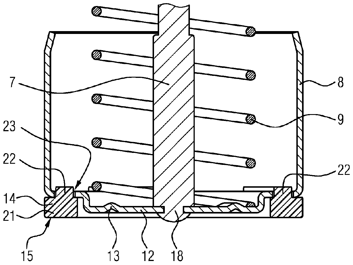
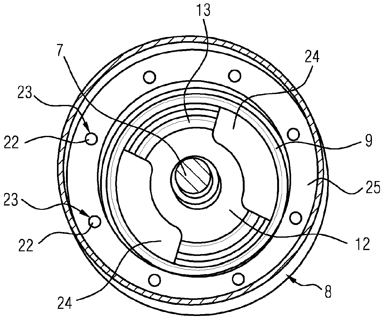
[0019] figure 1 A valve is shown comprising a housing 1 with a socket 2 integrally formed for electrical connection of the valve. Furthermore, the housing 1 has a formed flange 3 and three bores 3 a, via which the housing 1 is flanged to a turbocharger (not shown) in the region of the bypass line 4 . A solenoid 5 with a coil 6 and a metal rod 7 is arranged in the housing 1 . The metal rod 7 is connected to a pot-shaped piston 8 . When the solenoid 5 is not actuated, the spring 9 pretensions the piston 8 against the valve seat 10 in order to close the bypass line 4 so that no medium comes from the bypass line 4 and no medium can flow from the bypass line into the line 11 . The spring 9 is supported here on the solenoid 5 and on the piston 8 , wherein the piston 8 has a centering bead 13 in its base 12 for centering the spring 9 . The piston 8 has a wall thickness of 0.5 mm. Arranged on the outside of the bottom 12 is an axially protruding annular seal 14 made of PPA. In t...


PUM


Abstract

The invention relates to a valve having a housing (1), a solenoid (5) disposed in the housing (1), a pin (7) that can be moved by the solenoid, a piston (8) connected to the pin (7), and a seal. The piston (8) consists of a metal and has a seal (14) which consists of a material different from that of the piston (8), said seal (14) being arranged in the head region (12) of the piston (8).

Description

technical field [0001] The invention relates to a valve having a housing, a solenoid arranged in the housing, a rod movable by the solenoid and a piston connected to the rod. Background technique [0002] Such valves are primarily used as air diversion valves on turbochargers in motor vehicles in order to release the bypass to the intake side during coasting / coasting, and are therefore known. In order to prevent excessive braking of the turbocharger, but also to ensure a fast start-up, fast opening and closing of the valve is an important prerequisite. Especially when closing it is important that an immediate closing is achieved by pressing the piston against the valve seat. Therefore, the piston is made of plastic for weight reasons. The valve seat is formed by the housing of the turbocharger, to which the valve is flanged. Due to the high number of closing cycles and the operating-related temperature stresses required during the service life, high demands are placed on ...

Claims


Application Information

Patent Timeline
Patent Type & Authority Applications(China)
IPC IPC(8): F16K39/02F02B37/16F16K31/06F16K1/46
CPCF02B37/16F16K1/46F16K1/465F16K31/0655F16K31/0686F16K39/024F16K31/0693
Inventor R·博南诺
Owner VTESCO TECH GMBH
Learn More