
Self-releasing power line with overcurrent protection and battery pack

A technology of automatic disengagement and over-current protection, which is applied in the direction of batteries, battery pack components, circuits, etc., can solve the problems of ineffective suppression of battery explosion and fire, complex system configuration, battery short circuit, etc., and reduce the use of circuit insurance components , high safety, and the effect of reducing harm

Pending Publication Date: 2019-08-02
SUZHOU ANKAO ENERGY
View PDF0 Cites 0 Cited by
  • Summary
  • Abstract
  • Description
  • Claims
  • Application Information

AI Technical Summary

Problems solved by technology

[0004] However, there are still some common problems in the whole battery system, such as complex system configuration, hidden danger of battery short circuit; too many preventive measures in the battery pack, fuses, contactors, etc. occupy too much space in the battery pack and have misjudgments Risk; components such as explosion-proof valves cannot effectively suppress the explosion and fire of the battery in practical applications; after the battery is thermally out of control, the heat is exported from the power line to cause further loss of control of adjacent battery modules or even adjacent battery packs

Method used


Image

  • Self-releasing power line with overcurrent protection and battery pack
  • Self-releasing power line with overcurrent protection and battery pack
  • Self-releasing power line with overcurrent protection and battery pack

Examples


Embodiment Construction

[0052] The present application will be described in further detail below through specific embodiments in conjunction with the accompanying drawings. The present application can be implemented in many different forms, and is not limited to the implementation manner described in this embodiment. The purpose of providing the following specific embodiments is to facilitate a clearer and more thorough understanding of the disclosure of the present application, wherein the words indicating orientation such as up, down, left, and right are only for the positions of the structures shown in the corresponding drawings.

[0053] However, those skilled in the art may recognize that description of one or more of the specific details may be omitted, or other methods, components or materials may also be used. In some instances, some implementations were not described or described in detail.

[0054] In addition, the technical features and technical solutions described herein can also be com...


PUM

PropertyMeasurementUnit
melting pointaaaaaaaaaa

Abstract

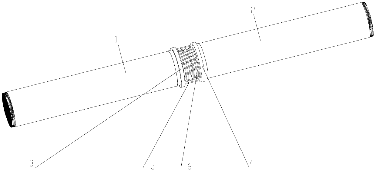
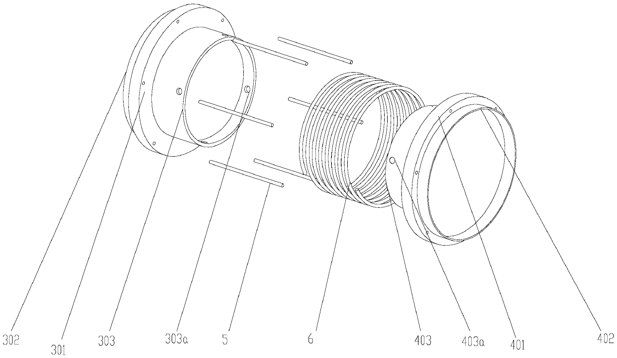
The invention discloses a self-releasing power line with overcurrent protection and a battery pack. The self-releasing power line comprises a left line segment, a right line segment, a left conductivesleeve which is fixedly and electrically connected to one end part of the left line segment, a right conductive sleeve which is fixedly and electrically connected to one end part of the right line segment and fixedly connected with the left conductive sleeve through a buckle assembly, at least one fusible metal wire connecting the left conductive sleeve and the right conductive sleeve and a compression spring which is clamped between the left conductive sleeve and the right conductive sleeve. In the axial direction of the compression spring, the locking force of the buckle assembly to the left conductive sleeve and the right conductive sleeve is less than the elastic force of the compression spring to the left conductive sleeve and the right conductive sleeve, and the sum of the locking force of the buckle assembly to the left conductive sleeve and the right conductive sleeve and the total breaking force of all the fusible metal wires is greater than the elastic force of the compression spring to the left conductive sleeve and the right conductive sleeve. Aiming at the deficiency in the prior art, the self-releasing power line with overcurrent protection and the battery pack are put forward. The automatic cut-off function after short-circuit overcurrent is additionally arranged on the power line without affecting the flow conductivity of the power line.

Description

technical field [0001] The present application relates to a self-disconnecting power line and battery pack with overcurrent protection. Background technique [0002] The rapid development of new energy vehicles has led to the rapid development of the power battery industry and a large number of secondary industries, such as power wiring harnesses for overcurrent. [0003] The rapid development of the new energy industry has also brought a series of problems that need to be solved, such as safety issues in the field of power batteries, and safety hazards caused by complex battery system integration. Especially in recent years, there have been frequent incidents of power battery short-circuit fires. But fortunately, with the innovation of science and technology and the gradual improvement of people's safety awareness, the government and various new energy industries are gradually strengthening safety management. The specific manifestations on the battery pack include adding ...

Claims


Application Information

Patent Timeline
Patent Type & Authority Applications(China)
IPC IPC(8): H01R13/68H01R13/627H01R13/635H01R24/00H01M2/34
CPCH01R13/68H01R13/6278H01R13/635H01R24/00H01M2200/103H01M50/581Y02E60/10
Inventor 张尖杨加松顾江娜关云来李相哲娄豫皖许玉林王爱淑
Owner SUZHOU ANKAO ENERGY
Learn More