
Method for determining minimum safety flow of turbine low-pressure cylinder

A minimum flow, low-pressure cylinder technology, applied in the direction of instrumentation, calculation, electrical digital data processing, etc., can solve the inaccurate determination of the peak-shaving depth of thermal power units, the inaccurate determination of the minimum flow rate of low-pressure cylinders, and the inability to fully utilize the peak-shaving potential of thermal power units And other issues

Active Publication Date: 2019-08-02
JILIN ELECTRIC POWER RES INST +1
View PDF5 Cites 5 Cited by
  • Summary
  • Abstract
  • Description
  • Claims
  • Application Information

AI Technical Summary

Problems solved by technology

[0007] Aiming at the inaccurate determination of the minimum flow rate of the low-pressure cylinder, that is, the inaccurate determination of the peak-shaving depth of the thermal power unit, and the inability to fully utilize the peak-shaving potential of the thermal power unit, the present invention creatively proposes a method for determining the minimum safe flow rate of the low-pressure cylinder of a steam turbine. The solid coupling method calculates the static strength evaluation indexes such as stress and strain of the low-pressure cylinder blade, and determines the dynamic strength evaluation indexes such as frequency and mode shape through the modal analysis method, and combines the static strength index and the dynamic strength index to determine the minimum safe flow rate of the low-pressure cylinder of the steam turbine , which can not only give full play to the ability of the unit to participate in peak regulation, but also ensure the safe and stable operation of the unit

Method used


Image

  • Method for determining minimum safety flow of turbine low-pressure cylinder
  • Method for determining minimum safety flow of turbine low-pressure cylinder
  • Method for determining minimum safety flow of turbine low-pressure cylinder

Examples


Embodiment

[0100] Embodiment: determine the minimum safe flow of a certain 300MW steam turbine low-pressure cylinder through a method for determining the minimum safe flow of the low-pressure cylinder of the steam turbine, including the following steps:

[0101] (1) Model pre-processing: For a 300MW steam turbine unit, extract the blade data and operating parameters, and establish the final stage flow field of the unit's low-pressure cylinder and the solid structure model of the blade. The steps are as follows:

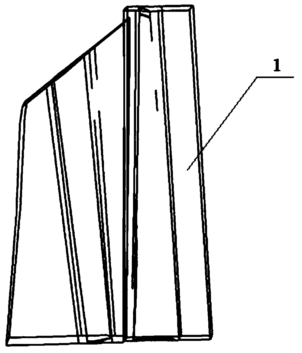
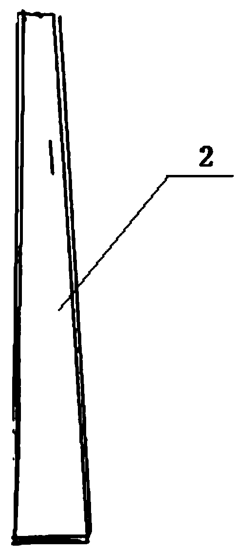
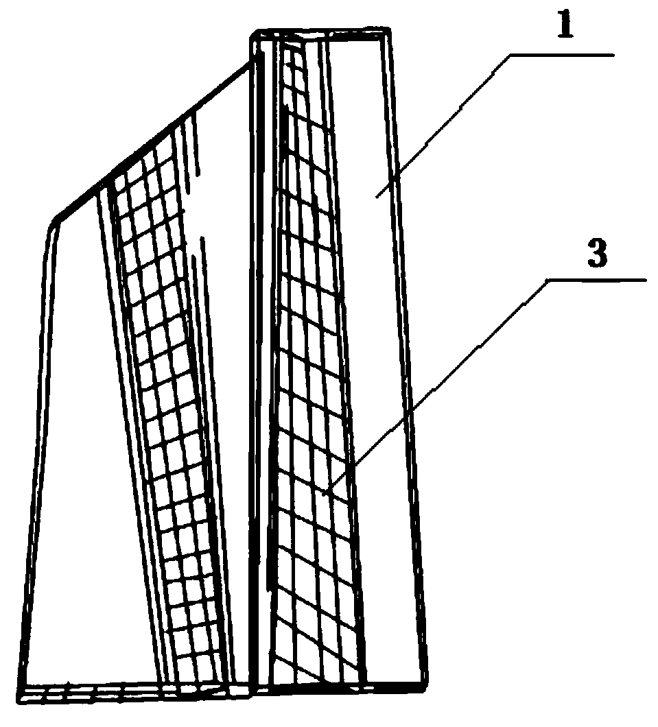
[0102] (1.1) Through the three-dimensional scanning of a 300MW steam turbine final stage blade model to form data points, set up in Gambit as attached figure 1 shown, the physical model and the attached figure 2 The moving blade structure model shown, the number of moving blades is 80, the number of stationary blades is 52, and the blade height is 906mm;

[0103] (1.2) Since the blade model is periodic, in order to save calculation time, a single-channel physical model is esta...


PUM


Abstract

The invention discloses a method for determining minimum safety flow of a turbine low-pressure cylinder. The method includes: combining the static strength index and the dynamic strength index; determining the minimum safety flow of the turbine low-pressure cylinder; establishing a numerical model, analyzing a final-stage blade flow field under a small-flow working condition, analyzing final-stageblade stress and strain under the small-flow working condition, determining the minimum safety flow of the low-pressure cylinder under a static strength condition, performing modal analysis on the final-stage blade under the small-flow working condition, combining dynamic strength and static strength to determine the minimum safety flow of the low-pressure cylinder under a deep peak regulation working condition, and the like. The minimum safety flow of the low-pressure cylinder under the working condition of deep peak regulation can be rapidly and accurately determined, the problem that the minimum safety flow is not accurately determined from the flow field level or the structure side face is solved, safe and stable operation of a unit is guaranteed, the potential of deep peak regulationof the unit can be fully exerted, the wind abandoning rate is reduced, and more new energy can be generated in a grid-connected mode.

Description

technical field [0001] The invention is applicable to the field of absorbing new energy, determining the deep peak-shaving range of a traditional coal-fired unit, and ensuring the safety of the unit's peak-shaving, and in particular relates to a method for determining the minimum safe flow rate of a low-pressure cylinder of a steam turbine. Background technique [0002] With the rapid development of the global economy and the increasing demand for energy, countries around the world are more interested in wind energy, solar energy and other new energy grid-connected power generation. In order to absorb more new energy and increase the grid-connected power generation capacity of new energy, traditional coal-fired units have been operating under peak-shaving conditions for a long time. The peak shaving range is to determine the minimum flow rate of the low-pressure cylinder, and determining the minimum flow rate of the low-pressure cylinder is an important factor affecting the ...

Claims


Application Information

Patent Timeline
IPC IPC(8): G06F17/50
CPCG06F30/17G06F30/20
Inventor 赵金峰曹丽华司和勇王文龙豆中州杨杉鲁绍博王艳红胡鹏飞王占洲李盼
Owner JILIN ELECTRIC POWER RES INST
Learn More