Flexible electromagnetic wave shielding material and manufacturing method therefor
一种屏蔽材料、电磁波的技术,应用在屏蔽材料、磁场/电场屏蔽、分散在不导电无机材料中的导电材料等方向,能够解决难以表现伸缩性、柔软性不足、难以完全表现电磁波屏蔽性能等问题,达到容易采用、伸缩性卓越、优秀电磁波屏蔽性能的效果
- Summary
- Abstract
- Description
- Claims
- Application Information
AI Technical Summary
Problems solved by technology
Method used
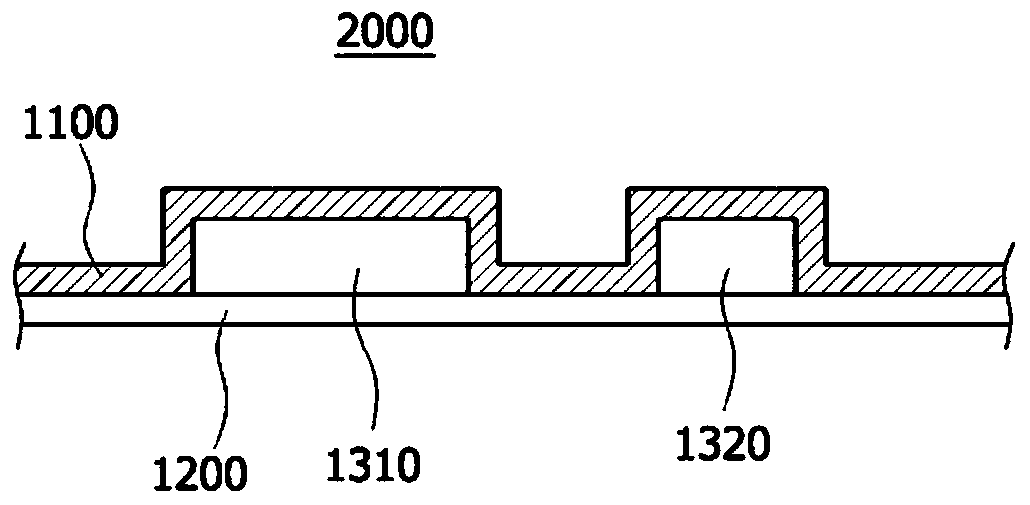
Image


Examples
Embodiment 1
[0067] First, in order to prepare a spinning solution, polyvinylidene fluoride and polyurethane were mixed in a weight ratio of 1:1 as a fiber-forming component, and in 85 g of dimethylacetamide and acetone at a weight ratio of 70:30, in 80 At a temperature of °C, 15 g of the fiber-forming component was dissolved for 6 hours using a bar magnet to prepare a mixed solution. In the mixed solution, 50 parts by weight of nickel rods (rods) having an average diameter of 1 μm and an average length of 2.5 μm were mixed using a mixer with respect to 100 parts by weight of the fiber-forming component. Put the spinning solution into the solution box of the electrospinning device, and spit it out at a speed of 15 μl / min / hole. At this time, the temperature in the spinning section is kept at 30°C, the humidity is kept at 50%, the distance between the collector and the tip of the spinning nozzle is 20cm, and a high voltage generator is used to apply 40kV or more to the spinning nozzle group ...
Embodiment 2~22 and comparative example 1~3
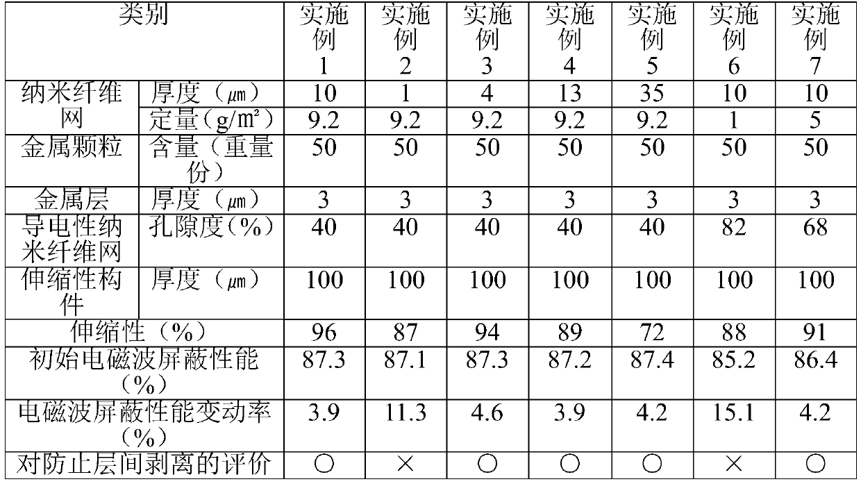
[0070] The same implementation and manufacture as in Example 1, but as shown in Table 1 to Table 4 below, the thickness and weight of the nanofibrous web, the content of metal particles, the porosity of the conductive nanofibrous web, the thickness of the metal layer, and the stretchable member were changed. The thickness, etc., manufactured the flexible electromagnetic wave shielding materials shown in Table 1 to Table 4.
experiment example 1
[0072] The following physical properties were measured for the flexible electromagnetic wave shielding materials manufactured in Examples and Comparative Examples, and are shown in Tables 1 to 4 below.
[0073] 1. Elasticity (elastic recovery rate) evaluation
[0074] For the flexible electromagnetic wave shielding material manufactured according to the embodiment and the comparative example, by UTM (Universal Testing Machine (Universal Testing Machine), Instron Corporation, 3343), make it stretch 50% and remove the external force, according to the following mathematical formula 1 Evaluate scalability.
[0075] [mathematical formula 1]
[0076] Elasticity (elastic recovery rate) (%) = [(lengthened by external force) - (length after removal of external force)] / [(lengthened by external force) - (initial length)] × 100 (%) )
[0077] 2. Initial electromagnetic wave shielding performance
[0078] Regarding the flexible electromagnetic wave shielding materials manufactured ac...
PUM
| Property | Measurement | Unit |
|---|---|---|
| diameter | aaaaa | aaaaa |
| porosity | aaaaa | aaaaa |
| diameter | aaaaa | aaaaa |
Abstract
Description
Claims
Application Information
 - R&D
- Intellectual Property
- Life Sciences
- Materials
- Tech Scout
- Unparalleled Data Quality
- Higher Quality Content
- 60% Fewer Hallucinations
Browse by: Latest US Patents, China's latest patents, Technical Efficacy Thesaurus, Application Domain, Technology Topic, Popular Technical Reports.
© 2025 PatSnap. All rights reserved.Legal|Privacy policy|Modern Slavery Act Transparency Statement|Sitemap|About US| Contact US: help@patsnap.com