
Power supply management method and device

A technology for power supply management and power supply unit, which is applied in circuit devices, electrical digital data processing, electrical components, etc., and can solve the problems that managers cannot change and power load quota cannot be reconfigured.

Active Publication Date: 2021-03-05
NANNING FUGUI PRECISION IND CO LTD
View PDF6 Cites 0 Cited by
  • Summary
  • Abstract
  • Description
  • Claims
  • Application Information

AI Technical Summary

Problems solved by technology

When one of the PoE switches no longer needs to be powered by the corresponding PSU, the extra power load of the corresponding PSU cannot be reconfigured for use by other PoE switches;
[0005] (2) The priority of the power supply port corresponding to each PSU in the EPS is preset and cannot be changed by the administrator; and

Method used


Image

  • Power supply management method and device
  • Power supply management method and device
  • Power supply management method and device

Examples


Embodiment Construction

[0025] In order to more clearly understand the above objects, features and advantages of the present invention, the present invention will be described in detail below in conjunction with the accompanying drawings and specific embodiments. It should be noted that, in the case of no conflict, the embodiments of the present application and the features in the embodiments can be combined with each other.

[0026] In the following description, many specific details are set forth in order to fully understand the present invention, and the described embodiments are only a part of the embodiments of the present invention, rather than all the embodiments. Based on the embodiments of the present invention, all other embodiments obtained by persons of ordinary skill in the art without making creative efforts belong to the protection scope of the present invention.

[0027] Unless otherwise defined, all technical and scientific terms used herein have the same meaning as commonly understo...


PUM


Abstract

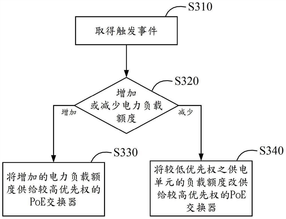
A method for managing a power supply comprises an Extension Power over Ethernet System receiving a trigger event. A determination is made as to whether the trigger event would cause a power budget of a power supply management device to increase or decrease; if the power is increased, the power is provided to a switch with a higher priority; if the power is decreased, power can be provided to a switch with a higher priority from a lower priority. A device for power supply management is also disclosed, the method and the device can effectively allocate power as required and avoid equipment overload.

Description

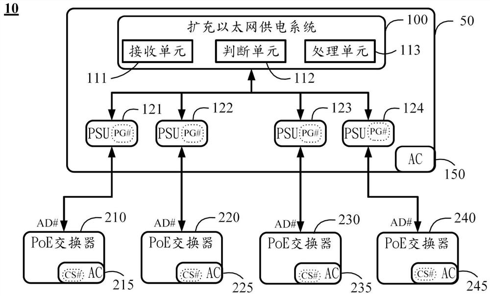
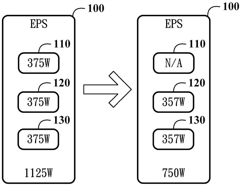
technical field [0001] The present invention relates to the technical field of communication, in particular to a power management mechanism of a Power over Ethernet (PoE) switch (Switch) Background technique [0002] Extended Power over Ethernet system (Extension PoE System, EPS) is used to provide additional power to power supply equipment (Power Sourcing Equipment, PSE) switches, such as PoE switches, and can be based on its own power load (Power Budget) Allocate (Allocate) the power load quota to the PoE switch or recycle (Recycle) the power load quota from the PoE switch. [0003] However, existing EPS has the following disadvantages: [0004] (1) The EPS has a plurality of power supply units (Power Supply Unit, PSU), which can supply power to multiple PoE switches, and the power load of each PSU is fixed. When one of the PoE switches no longer needs to be powered by the corresponding PSU, the extra power load of the corresponding PSU cannot be reconfigured for use by ...

Claims


Application Information

Patent Timeline
Patent Type & Authority Patents(China)
IPC IPC(8): H04L12/10
CPCH04L12/10G06F1/263G06F1/28G06F1/30G06F1/3209G06F1/3287H02J3/00Y02B70/30Y04S20/20Y02D10/00
Inventor 陈宏达许传政
Owner NANNING FUGUI PRECISION IND CO LTD
Learn More