Cast-in-place concrete separator special for composite light-weight (CL)

A separator and concrete technology, which is applied in the construction, building structure, building material processing and other directions, can solve the problems affecting the apparent state of pouring and building safety, and the pouring of the outer concrete protective layer is not compact, so as to improve the practicability. Effect

Pending Publication Date: 2019-07-30
河南西艾尔墙体科技有限公司
View PDF0 Cites 2 Cited by
  • Summary
  • Abstract
  • Description
  • Claims
  • Application Information

AI Technical Summary

Problems solved by technology

[0003] At present, in the cast-in-situ concrete walls of the CL composite thermal insulation structure, the concrete on both sides of the CL grid slab is poured at the same time, but during the casting process, the inside of the CL shear wall is a traditional shear wall, and the outside is an insulation board. Concrete protective layer, the thickness of the outer concrete protective layer is 50-60mm, and the CL grid plate in the concrete protective layer is provided with steel wire mesh sheets and connecting rods, which are equipped with concrete machines when ordinary concrete is poured. The process contains a large amount of coarse aggregate, and the 50-60mm thick concrete protective layer should not be vibrated during the casting process, which will cause the outer concrete protective layer to be poured incompletely, which will seriously affect the apparent state of the completed pouring and building safety

Method used


Image

  • Cast-in-place concrete separator special for composite light-weight (CL)
  • Cast-in-place concrete separator special for composite light-weight (CL)
  • Cast-in-place concrete separator special for composite light-weight (CL)

Examples


Embodiment 1

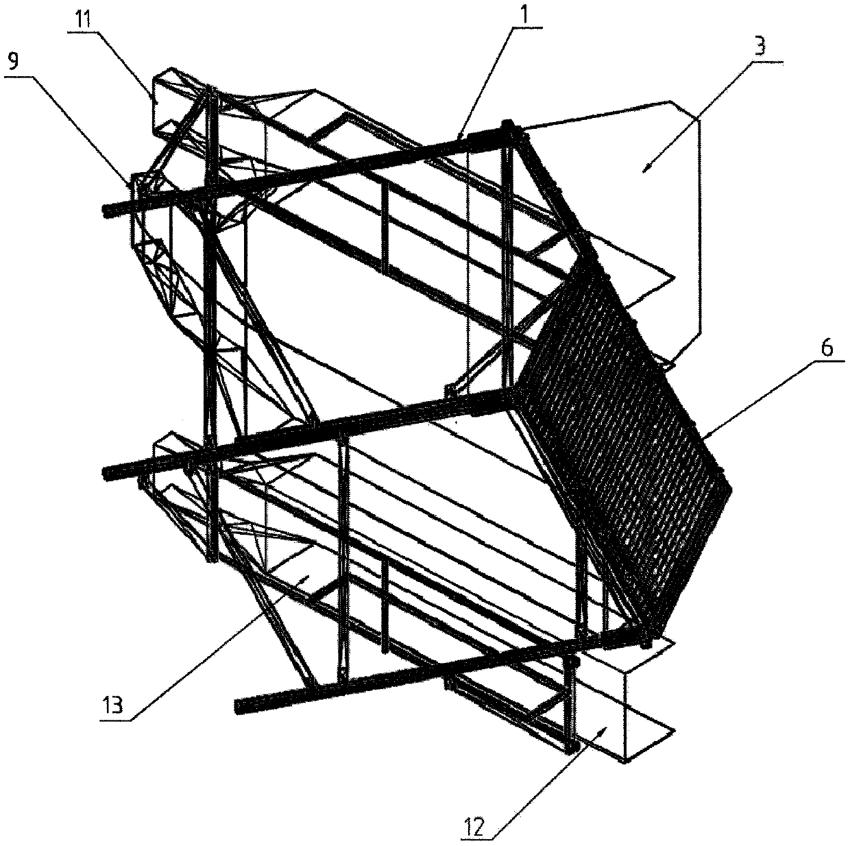
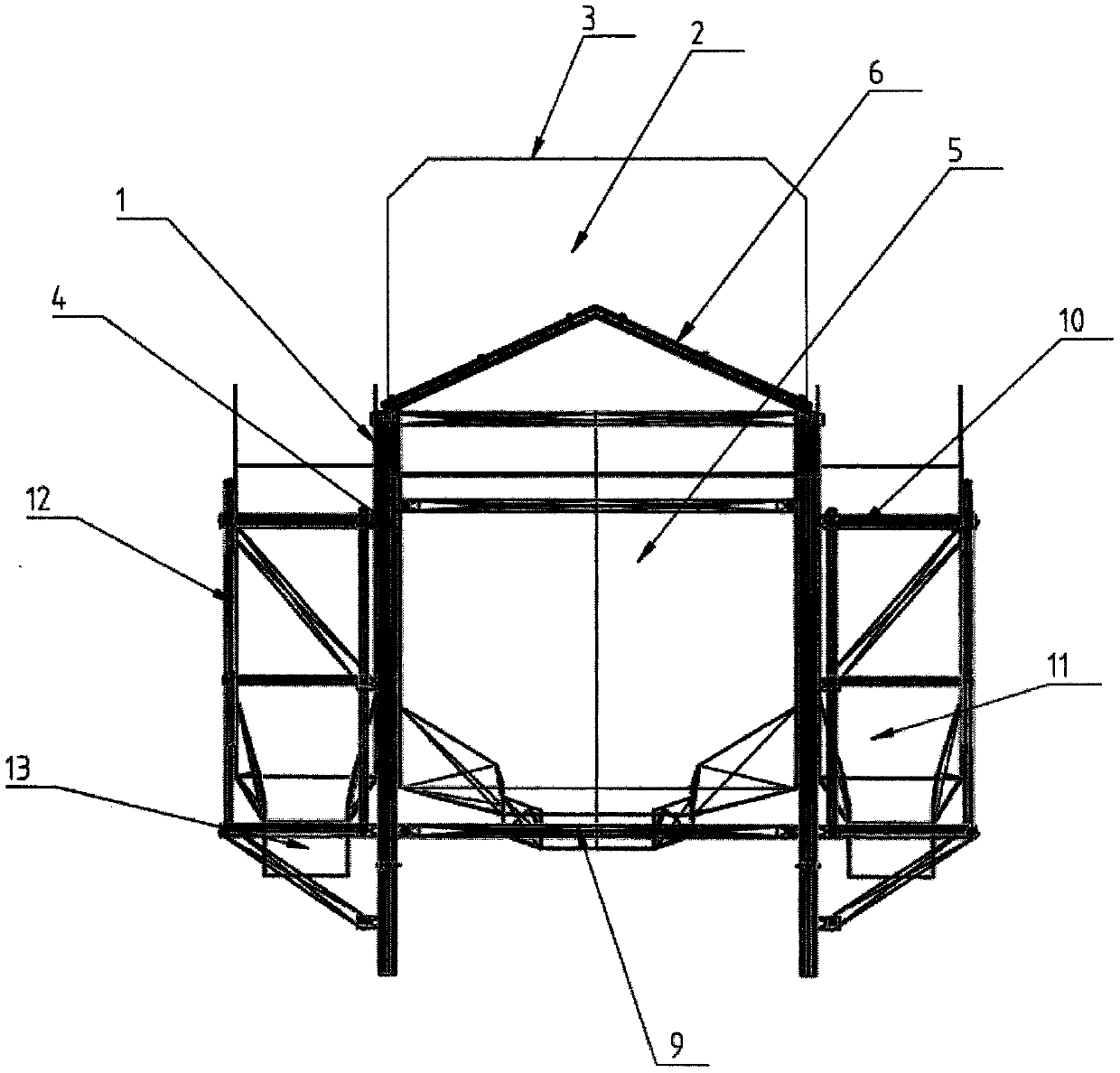
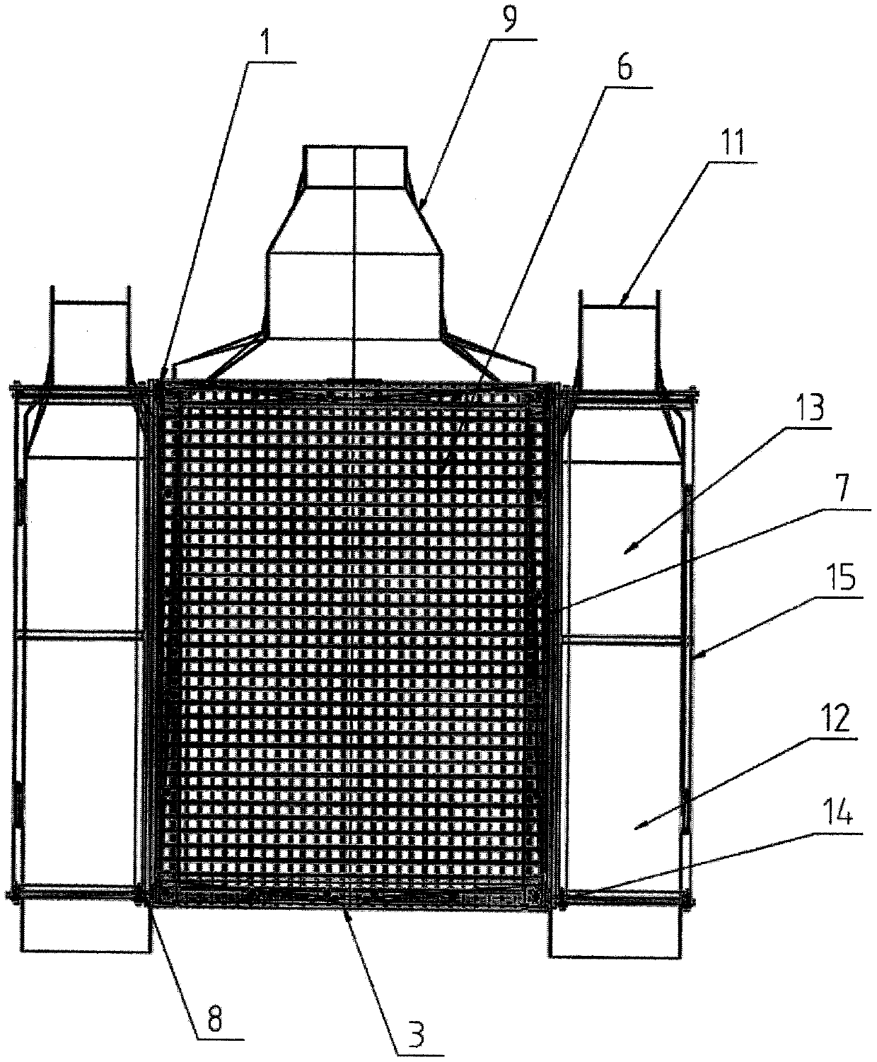
[0026] Such as Figure 1-5 A CL-specific cast-in-place concrete separator shown includes a separator bracket 1, a grouting port 2 is provided on the top of the separator bracket 1, and an overflow prevention baffle 3 is provided on the outside of the grouting port 2. A separation device 4 is provided at the bottom of the grouting port 2;

[0027] Described separation device 4 comprises separation chamber 5, and described separation chamber 5 is provided with separation piece 6, and described separation piece 6 is made of the steel wire mesh sheet of different spacing, and described separation piece 6 is provided with damping pad 7, The shock absorbing pad 7 is provided with a crimping metal buckle 8, and the separating sheet 6 is arranged in the form of a herringbone slope;

[0028] The bottom of the separation chamber 5 is provided with a first slurry outlet 9, and the outer side of the first slurry outlet 9 is provided with a flow diversion groove 10, and the end of the flo...

Embodiment 2

[0036] On the basis of the above embodiments, further, the separator 6 can also be set in the form of an arc surface;

[0037] Including a separator bracket 1, the top of the separator bracket 1 is provided with a grouting port 2, the outside of the grouting port 2 is provided with an anti-overflow baffle 3, and the bottom of the grouting port 2 is provided with a separation device 4;

[0038] Described separation device 4 comprises separation chamber 5, and described separation chamber 5 is provided with separation piece 6, and described separation piece 6 is made of the steel wire mesh sheet of different spacing, and described separation piece 6 is provided with damping pad 7, The shock absorbing pad 7 is provided with a crimping metal buckle 8, and the separating sheet 6 is arranged in the form of a herringbone slope;

[0039] The bottom of the separation chamber 5 is provided with a first slurry outlet 9, and the outer side of the first slurry outlet 9 is provided with a f...

Embodiment 3

[0042] Different from Embodiment 1, the connection form between the separation chamber 5 and the separation sheet 6 can also be connected by a mortise and tenon slot;

[0043] Including a separator bracket 1, the top of the separator bracket 1 is provided with a grouting port 2, the outside of the grouting port 2 is provided with an anti-overflow baffle 3, and the bottom of the grouting port 2 is provided with a separation device 4;

[0044]Described separation device 4 comprises separation chamber 5, and described separation chamber 5 is provided with separation piece 6, and described separation piece 6 is made of the steel wire mesh sheet of different spacing, and described separation piece 6 is provided with damping pad 7, The shock absorbing pad 7 is provided with a crimping metal buckle 8, and the separating sheet 6 is arranged in the form of a herringbone slope;

[0045] The bottom of the separation chamber 5 is provided with a first slurry outlet 9, and the outer side o...


PUM


Abstract

The invention discloses a cast-in-place concrete separator special for composite light-weight (CL), and particularly relates to the field of building machinery. The cast-in-place concrete separator special for the CL comprises a separator bracket, a slip casting opening is formed in the top of the separator bracket, an overflowing-prevention baffle is arranged on the exterior of the slip casting opening, and a separating device is arranged at the bottom of the slip casting opening; the separating device comprises a separating cavity, a separating piece is arranged in the separating cavity, theseparating piece is made of steel wire meshes with different intervals, a shock pad is arranged on the separating piece, a blank pressing metal buckle is arranged on the shock pad, and the separatingpiece is arranged as a gable slope or arc structural mode; and a first slurry discharging groove is formed in the bottom of the separating cavity. According to the cast-in-place concrete separator special for the CL, the content of coarse aggregate in concrete after separation is reduced, vibration is suitable for being carried out on a concrete protection layer with the thickness of 50-60mm in the casting process, so that a concrete protection groove on the outer side of a CL shear wall is poured more densely, and the appearance is improved and the safety of building is improved.

Description

technical field [0001] The invention relates to the field of construction machinery, more specifically, the invention relates to a special cast-in-place concrete separator for CL. Background technique [0002] CL building structure system is a new type of composite wall building structure system, also known as composite thermal insulation reinforced welded grid concrete shear wall, which is a shear wall structure composed of CL wall panels and solid shear walls. Compared with other structures, the CL building structure system has the characteristics of environmental protection, energy saving (no clay bricks), earthquake resistance, light weight, and industrial production. The CL building system can not only meet the technical standards for energy saving of more than 75% stipulated by the state, but also solve the hidden dangers such as easy cracks, hollowing, leakage, and shedding that are commonly used in the current technology of external wall paste and external insulation...

Claims


Application Information

Patent Timeline
IPC IPC(8): E04G21/02
CPCE04G21/02
Inventor 尤书建谢腾腾芦莉刘磊明申遂马喆
Owner 河南西艾尔墙体科技有限公司
Why Eureka
Try Eureka