Eureka AIR delivers breakthrough ideas for toughest innovation challenges, trusted by R&D personnel around the world.

A large-span long cantilever conjoined structure and its construction technology

A technology of one-piece structure and long cantilever, which is applied in building construction, construction, and building materials processing, etc., can solve the problems of inconvenient direct application of large-span and long cantilever solutions, achieve a broad scope of application and development space, and meet earthquake resistance. Performance requirements, reasonable structure effect

Active Publication Date: 2017-03-01
香港华艺设计顾问(深圳)有限公司
View PDF7 Cites 0 Cited by
  • Summary
  • Abstract
  • Description
  • Claims
  • Application Information

AI Technical Summary

Problems solved by technology

In recent years, with the increasing diversification and complexity of architectural shapes, floor-to-ceiling towers below conjoined floors may appear smaller than the width of the upper floors in the direction of floor width, which will inevitably lead to the design experience of solving long-span and long cantilever solutions in the past. Not easy to apply directly to this new situation
That is to say, there is no directly corresponding floor-to-ceiling wall column as the support for the corresponding support position of the long-span and long-cantilever floor, and the existing technology and engineering experience are not enough to properly solve this problem

Method used


Image

  • A large-span long cantilever conjoined structure and its construction technology
  • A large-span long cantilever conjoined structure and its construction technology
  • A large-span long cantilever conjoined structure and its construction technology

Examples


Embodiment Construction

[0034] The specific implementation manners of the present invention will be further described in detail below in conjunction with the accompanying drawings.

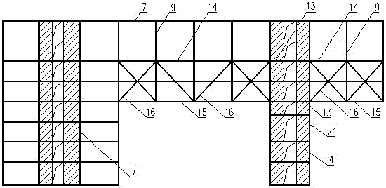
[0035] A kind of large-span long cantilever hybrid structure of the present invention, such as figure 1shown. Its structural plane is rectangular on the standard floor, and below the standard floor it is divided into two towers, one of which is a cylinder 4, which supports the upper long-span floor area and the long-cantilever floor area on its left and right sides respectively. Among them, the long-span floor area is composed of side-span steel truss 1, middle-span steel truss 2, steel frame beam 7, steel secondary beam 8, steel column 9 and steel truss floor deck 33; the long-cantilever floor area is composed of side-span steel truss 1. The middle span steel truss 2, the steel frame beam 7, the steel secondary beam 8, the steel column 9, the floor brace 12 and the steel truss floor deck 33.

[0036] The above-mention...


PUM


Abstract

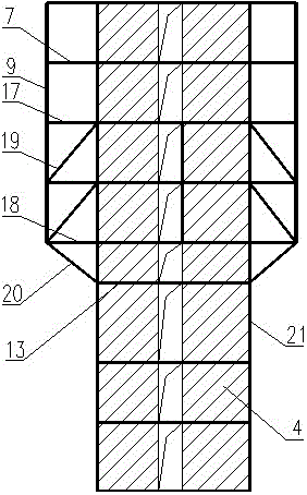
The invention discloses a large-span long-cantilever connection structure and a construction technique. The structure plane is arranged in the form of rectangle, two towers are arranged beneath the standard layer, wherein a tower is a cylinder body (4), the left and right sides of the tower respectively support a large-span and long-cantilever floor at the upper part, and the width of the cylinder body (4) is less than the width of the floor at the upper part, and the vertical face of the tower forms a model with a wide upper part and a narrow lower part; the other one tower is a framework shear wall structure. The large-span and long-cantilever is connected to the two towers through a side-span steel truss (1) and a middle-span steel truss (2) which are penetrated to each other. The side-span steel truss (1) is arranged within the scale of the cylinder (4), and supported on a supporting steel truss (3) extended from the cylinder (4) along the vertical direction. A steel framework beam (7) and a secondary steel beam (8) are equally arranged on the upper floor so as to form a floor cover supporting system. The floor cover adopts a steel bar truss floor support plate. The large-span long-cantilever connection structure solves the technical problem that the vertical face model is the connection structure with the wide upper part and the narrow lower part, and suitable for multi-layer and high rise buildings; moreover, the large-span long-cantilever connection structure has very strong universality and application scale.

Description

technical field [0001] The invention relates to a novel connected structure used in multi-storey and high-rise buildings, in particular to a large-span and long cantilever connected structure and construction technology, which belongs to the innovative technology in the field of large-span and long cantilever. Background technique [0002] In large and medium-sized cities, high-rise buildings are often restricted by various factors such as urban planning, site conditions, building functions, floor area ratio, height limit, fire protection, ventilation and lighting, etc., which objectively provide objective conditions for the diversification of building facade shapes. Correspondingly, the continuous innovation of new structural systems provides technical support for a wide variety of architectural shapes. When the building is divided into two towers at the bottom, and there is a large span between the two towers, the two floors of the standard floor are connected as a whole, ...

Claims


Application Information

Patent Timeline
Patent Type & Authority Patents(China)
IPC IPC(8): E04B1/342E04G21/00
Inventor 张伟刘俊周坚荣徐静高义奇
Owner 香港华艺设计顾问(深圳)有限公司
Why Eureka
Eureka Blog
Learn More