A drawing device for small viscosity glass tube

A glass tube and viscosity technology, which is applied in the vertical drawing of glass liquid, glass forming, glass manufacturing equipment, etc., can solve the problems of complicated operation, large production batch, difficult to control heating flow, etc., and achieve simple equipment configuration and structure. , The effect of improving the yield rate

Active Publication Date: 2021-10-01
HUBEI NEW HUAGUANG NEW INFORMATION MATERIALS CO LTD
View PDF8 Cites 0 Cited by
  • Summary
  • Abstract
  • Description
  • Claims
  • Application Information

AI Technical Summary

Problems solved by technology

This operation is feasible for high-viscosity glass, but it is difficult to perform head-on operation for low-viscosity glass by this method. Low-viscosity glass generally contains elements such as La, Zr, Ti, Ta, etc., and it is difficult to heat the flow rate. Control, when encountering crystallization glass, it will also cause glass crystallization to affect product quality.
[0006] The second is that they are only produced intermittently, rather than continuous production in small batches, and the operation is more difficult, and the stability of the product is difficult to guarantee
[0007] Literature patent CN200810018582 provides a method for drawing both quartz glass tubes and quartz glass rods, mainly because in the process of drawing quartz glass tubes by the continuous melting method, the production batch is relatively large, and it is not suitable for low-viscosity glass tube materials small batch production

Method used


Image

  • A drawing device for small viscosity glass tube
  • A drawing device for small viscosity glass tube
  • A drawing device for small viscosity glass tube

Examples


Embodiment Construction

[0028] Embodiments of the present invention will be further described below in conjunction with the accompanying drawings.

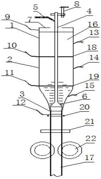
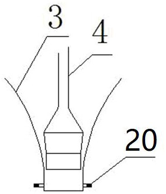
[0029] implemented as Figure 1 to Figure 5 shown. A low-viscosity glass tube drawing device of the present invention comprises a top-to-bottom connecting barrel 1, a viscosity adjusting barrel 2 and a molding die 3, a glass tube outer diameter detection device 21 is arranged below the molding die 3, It has the function of detecting the outer diameter of the tube. A glass tube traction device 22 is provided below the glass tube outer diameter detection device 21. A nozzle heating device 20 is provided at the outlet below the forming mold. The nozzle heating device 20 is a strip heating device. The material connecting cylinder 1, the viscosity adjusting cylinder 2 and the forming mold 3 are all equipped with electrodes correspondingly, which can be directly energized and heated, wherein the viscosity adjusting cylinder 2, the material connecting cylinder...


PUM

PropertyMeasurementUnit
thicknessaaaaaaaaaa
heightaaaaaaaaaa

Abstract

The title of the present invention is a kind of drawing device of small viscosity glass tube. It mainly solves the problem of small-batch drawing of small-viscosity optical glass tubes. Its main features are: including a top-to-bottom, connected as one, using a perforated partition to isolate the receiving cylinder, viscosity adjusting cylinder, forming mold, and nozzle heating device, ventilation pipe and glass tube traction device; nozzle The heating device is set on the discharge nozzle of the forming mold; the ventilation pipe is located on the central axis of the receiving cylinder, the viscosity adjustment cylinder, the forming mold and the nozzle heating device, and the lower end of the ventilation pipe is provided with the discharge nozzle of the forming mold The spindle body at the lower end of the matched air pipe; the glass tube traction device is arranged under the molding die. The invention utilizes the platinum self-heating to maintain the fluidity of the glass liquid, and has the characteristics of small size, simple structure, convenient installation, flexible use, and low difficulty in operation. The device can not only draw low-viscosity optical glass tubes but also low-viscosity optical glass rods.

Description

technical field [0001] The invention belongs to the technical field of forming glass tubes, in particular to a small-viscosity optical glass tube drawing device, which is mainly used for small-batch drawing and forming of low-viscosity optical glass tubes. Background technique [0002] At present, many glass tubes are widely used. Traditional glass tubes are mainly made of quartz glass and high borosilicate glass, and the output is generally more than 5 tons per day. With the development of science and technology, there are more and more requirements for the quality and physical and chemical properties of glass tubes of different varieties and specifications in certain technical fields, such as optical fiber panels, image inverters, light cones and other fibers used in low-light night vision. Optical components and glass tubing required for the imaging bundle fibers of endoscopes used in medical and industrial diagnostics have their own stringent technical standards. And th...

Claims


Application Information

Patent Timeline
Patent Type & Authority Patents(China)
IPC IPC(8): C03B15/14
CPCC03B15/14
Inventor 胡弦周希光王亮寇小勇翟军
Owner HUBEI NEW HUAGUANG NEW INFORMATION MATERIALS CO LTD
Why Eureka
Try Eureka