Cutting pile rebar cage welding device

A technology for welding devices and steel bars, which is applied in the direction of auxiliary devices, welding equipment, auxiliary welding equipment, etc., can solve the problems of heavy vertical steel bars, vertical steel bar inclination, etc., achieve convenient welding operations, low manufacturing costs, and improve welding processing The effect of quality and welding speed

Active Publication Date: 2019-07-30
MCC5 GROUP CORP SHANGHAI
View PDF8 Cites 0 Cited by
  • Summary
  • Abstract
  • Description
  • Claims
  • Application Information

AI Technical Summary

Problems solved by technology

[0003] In view of this, the object of the present invention is to provide a welding device for a pile-cut reinforcement cage to solve the technical problem in the prior art that the vertical reinforcement tends to be inclined during welding due to the heavy weight of the vertical reinforcement when the pile-cut reinforcement cage is welded

Method used


Image

  • Cutting pile rebar cage welding device
  • Cutting pile rebar cage welding device
  • Cutting pile rebar cage welding device

Examples


Embodiment 1

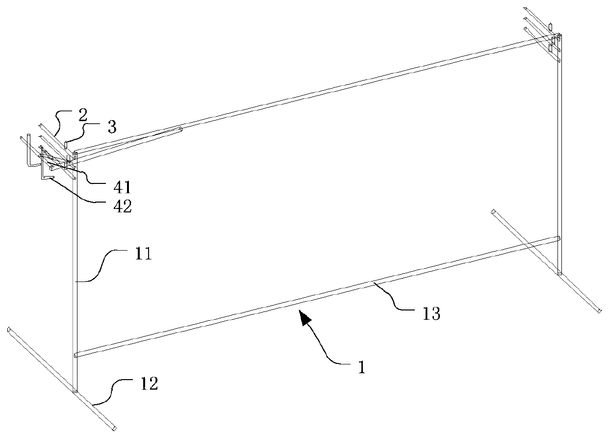
[0025] refer to figure 1 The utility model discloses a welding device for pile-cutting steel bar cage, which is used for welding the pile-cutting steel bar cage. In this embodiment, a steel bar cage for cutting piles with 6 vertical steel bars is taken as an example to describe a welding device suitable for such a steel bar for cutting piles. The welding device for pile-cutting reinforcement cage in this embodiment includes a bracket 1 , a first horizontal positioning rod group, a second horizontal positioning rod group and a pallet frame arranged on the bracket 1 . The bracket 1 includes a support frame and a cross bar 13. The number of support frames is two. The two support frames are arranged in parallel at a preset distance and are connected by the cross bar 13. The rod 11 is vertically connected to the horizontal feet 12 . In this embodiment, there are two horizontal bars 13 , which are respectively connected to the upper and lower ends of the two vertical bars 11 . Th...

Embodiment 2

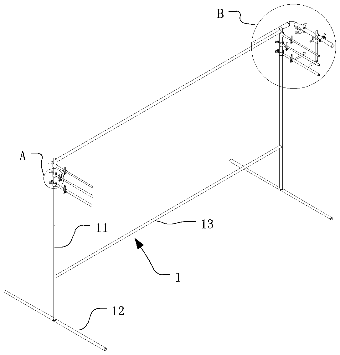
[0030] The structure of this embodiment is the same as that of the bracket 1 of the first embodiment, and the difference from the first embodiment is that the respective multiple horizontal positioning rods 2 of the first horizontal positioning rod group and the second horizontal positioning rod group are movably adjustable in height. On the bracket 1 , the positioning column 3 is movably arranged on the horizontal positioning rod 2 , and the height of the pallet frame is movably arranged on the bracket 1 .

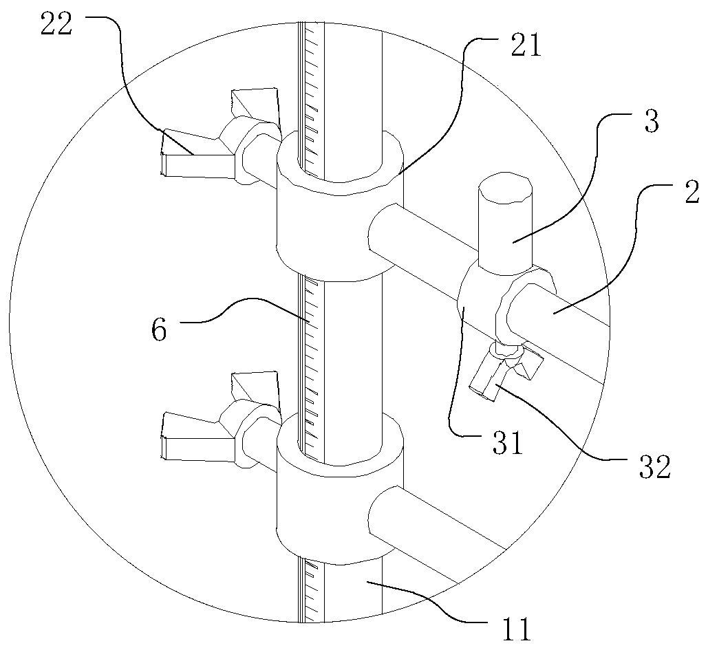
[0031] refer to Figure 2-5, This embodiment also takes a pile-cutting steel cage with six vertical steel bars 71 as an example to describe a welding device suitable for this kind of pile-cutting steel cage. Three horizontal positioning rods 2 are respectively provided at the upper end of each vertical rod 11 , and the heights of the three horizontal positioning rods 2 on the vertical rod 11 can be adjusted. Specifically, one end of the horizontal positioning rod 2 is pr...


PUM


Abstract

The invention relates to a cutting pile rebar cage welding device comprising a bracket, a first horizontal positioning rod group, a second horizontal positioning rod group and a layer board frame, wherein the first horizontal positioning rod group, the second horizontal positioning rod group and the layer board frame are arranged on the bracket. The first horizontal positioning rod group and the second horizontal positioning rod group are spaced by a preset distance and are correspondingly arranged, the first horizontal positioning rod group and the second horizontal positioning rod group areused in cooperation to be used for arranging and supporting a plurality of vertical reinforcing bars when a cutting pile rebar cage is welded, the layer board frame and the second horizontal positioning rod group are located on the two opposite sides of the first horizontal positioning rod group, the layer board frame is arranged adjacent to the first horizontal positioning rod group, and the layer board frame is used for placing and supporting a layer board when the layer board frame is welded. The welding device can make the vertical reinforcing bars be evenly distributed and well support the vertical reinforcing bars, the problem about vertical rebar inclination does not occur during welding, the welding processing quality and the welding speed of the cutting pile rebar cage can be significantly improved, and the welding operation of the cutting pile rebar cage is convenient and safe.

Description

technical field [0001] The invention relates to the technical field of building construction components, and more particularly, to a welding device for cutting pile reinforcement cages. Background technique [0002] With the rapid development of domestic infrastructure, steel cages are more and more widely used in pile foundation construction. The cut pile is directly opened on the designed pile position, and its cross-section is circular. After the hole is formed, a steel cage is placed in the hole and concrete is poured. The pile-cutting reinforcement cage includes a support plate and a plurality of vertical steel bars. The multiple vertical steel bars are evenly distributed around the circumference and one end is welded on the support plate. The vertical steel bars of the pile-cutting steel cage have a larger diameter and a longer length. In the middle, due to the large weight, the vertical steel bars are easily inclined during welding, and the operation during welding i...

Claims


Application Information

Patent Timeline
Patent Type & Authority Applications(China)
IPC IPC(8): B23K37/04
CPCB23K37/0426
Inventor 柳建国
Owner MCC5 GROUP CORP SHANGHAI
Why Eureka
Try Eureka