
Experimental teaching device for measuring light velocity in light-guide fiber and measurement method

An optical fiber and experimental device technology, applied in optical radiation measurement, measurement device, teaching model, etc., can solve the problems of no fiber length, unstable regeneration signal waveform, inconsistent circuit delay, etc. Clear concept and intuitive effect of physical phenomena

Inactive Publication Date: 2019-07-26
朱世国
View PDF0 Cites 3 Cited by
  • Summary
  • Abstract
  • Description
  • Claims
  • Application Information

AI Technical Summary

Problems solved by technology

However, the method for measuring the speed of light in optical fibers provided by this paper and the instruments and equipment produced by related technologies have the following shortcomings: because the saturation depth of the crystal triode in the regeneration circuit is not deep enough, the waveform of the regeneration signal is unstable, resulting in unstable measurement data and measurement The result error is large; there is no teaching content of fiber length measurement, and the fiber length is a known given value
[0004] (1) The saturation depth of the crystal triode in the regenerative circuit is not deep enough, which makes the waveform of the regenerative signal unstable, resulting in unstable measurement data and large errors in measurement results
[0005] (2) There is no device for measuring the length of the optical fiber in the experiment of measuring the speed of light in the optical fiber
[0006] (3) When two delay measurements are performed with dual optical fibers, the circuit delays of the two measurements are inconsistent, which affects the measurement results of the optical signal transmission time in the optical fiber

Method used


Image

  • Experimental teaching device for measuring light velocity in light-guide fiber and measurement method
  • Experimental teaching device for measuring light velocity in light-guide fiber and measurement method
  • Experimental teaching device for measuring light velocity in light-guide fiber and measurement method

Examples


Embodiment Construction

[0037] In order to further understand the content, characteristics and effects of the present invention, the following examples are given, and detailed descriptions are as follows in conjunction with the accompanying drawings:

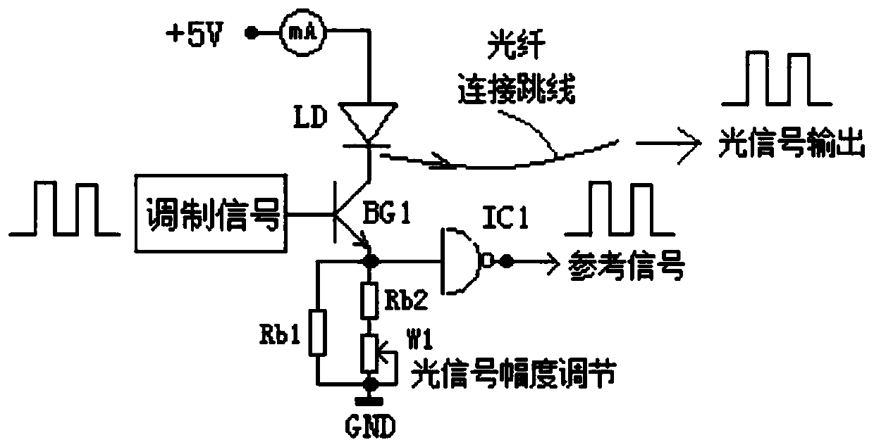
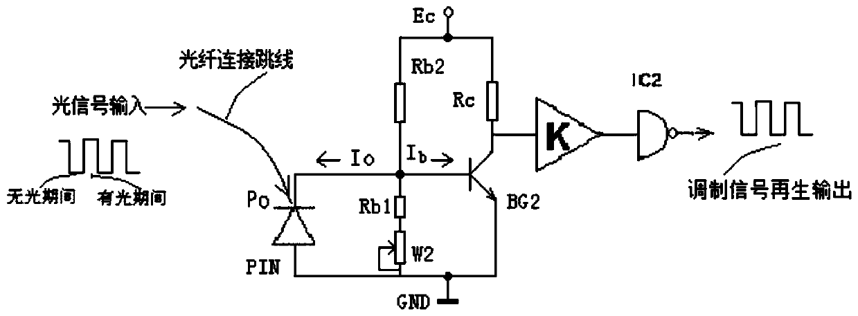
[0038] Aiming at the problems existing in the prior art, an experimental teaching device for measuring the speed of light in an optical fiber provided by the present invention is composed of the following parts: modulation signal source, electro-optic conversion of modulation signal and optical signal transmission module, optical fiber channel, photoelectricity of modulation signal Conversion and pulse width regeneration regulation circuit, XOR logic digital optical fiber length measurement module and optical power meter.

[0039] The application principle of the present invention will be described in detail below in conjunction with the accompanying drawings.

[0040] Such as figure 1 As shown, the experimental teaching device for measuring the speed...


PUM


Abstract

The invention belongs to the technical field of experimental teaching equipment, and discloses an experimental teaching device for measuring light velocity in an optical fiber. The device comprises amodulation signal source, a modulation signal electronic-to-optical conversion and optical signal transmission module, fiber channels, a modulation signal photoelectric conversion and pulse width regeneration adjustment circuit, an XOR logic digital fiber length measurement module and an optical power meter. Under the condition that the circuit delay is constant, the time delay of a receiving endregenerative signal relative to a transmitting end reference signal is measured twice by the fiber channels with lengths L1 and L2 respectively, and the transmission time of a modulation signal in theL1-L2 fiber length is obtained; the length of the optical fiber is measured by an XOR logic digital fiber length measurement instrument; the light velocity in the optical fiber can be calculated according to the transmission time of an optical signal in the optical fiber and the optical fiber length. The experimental teaching device for measuring the light velocity in the optical fiber has the advantages that the physical concept is clear, the physical phenomenon is visual, the measurement technology is novel, the data is stable, the result is accurate, and the device is an effective teachingplatform for cultivating students' sense of innovation consciousness and capacity.

Description

technical field [0001] The invention belongs to the technical field of experimental teaching equipment, and in particular relates to an experimental teaching device and a measuring method for measuring the speed of light in an optical fiber. Background technique [0002] The experiment of measuring the speed of light is a classic physics experiment, but there were only teaching instruments for measuring the speed of light in the air before, and the recognized value of the measurement result is c (300,000 km / s). The propagation speed of light in a transparent medium is not c, but c / n, where n is the refractive index of the transparent medium. In the teaching instrument industry, there is no instrument for measuring the propagation speed of light in transparent media with clear physical concept, feasible measurement method, reliable measurement technology, stable measurement data and accurate measurement results. Optical fiber is a transparent medium, and the successful devel...

Claims


Application Information

Patent Timeline
Patent Type & Authority Applications(China)
IPC IPC(8): G09B23/22G01J7/00
CPCG01J7/00G09B23/22
Inventor 朱世国
Owner 朱世国
Learn More