Automatic pushing type waste material collecting device for gear machining

A waste collection and automatic technology, applied in the direction of metal processing equipment, metal processing machinery parts, manufacturing tools, etc., can solve the problems of broken waste materials being brought out and falling into the ground, etc., to achieve reasonable guiding rebound characteristics, reasonable structure, and convenient Take out the collected effects

Active Publication Date: 2019-07-23
新昌县沃意科技有限公司
View PDF15 Cites 4 Cited by
  • Summary
  • Abstract
  • Description
  • Claims
  • Application Information

AI Technical Summary

Problems solved by technology

[0003] In the existing above-mentioned classified waste collection device, during the working process, it is unavoidable that the powdery debris generated during the processing will be brought into the device synchronously after the iron filing waste enters the recovery device, thus causing the strip-shaped waste to be discharged from the collection device again. When it is taken out, part of the broken waste will be taken out and fall to the ground. Therefore, the existing sorting waste and iron filings collection device needs to be reasonably designed under its sorting performance.

Method used


Image

  • Automatic pushing type waste material collecting device for gear machining
  • Automatic pushing type waste material collecting device for gear machining
  • Automatic pushing type waste material collecting device for gear machining

Examples


Embodiment

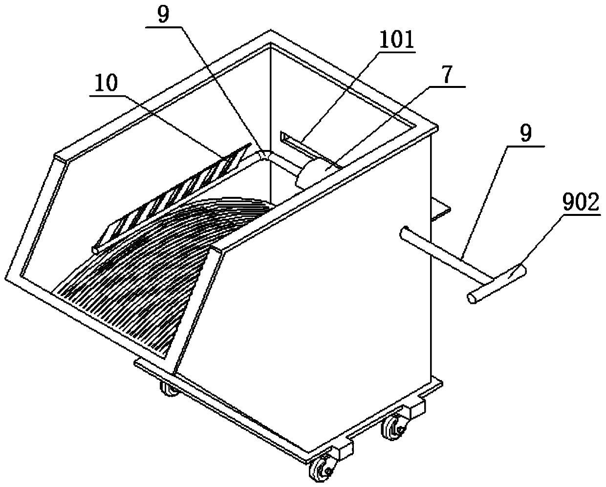
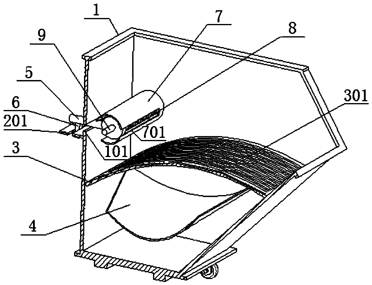
[0028] as attached figure 1 to attach Figure 9 Shown:

[0029] The present invention provides an automatic push-type waste collection device based on gear processing, including: a recovery cabin 1, a first guide groove 101, a discharge port 102, a guide edge 103, a side plate 2, a second guide groove 201, Distribution plate 3, drain 301, discharge plate 4, side extension rod 5, vertical rod 6, stop sleeve 7, third guide groove 701, spring 8, pull rod 9, stop ring 901, pull handle 902, pressure plate 10, Functional seat 11, push groove 1101, extrusion frame 1102, extrusion rod 1103, strength spring 1104, storage groove 1105 and pressure plate 1106; the recovery cabin 1 is a bucket cavity structure, and one side thereof is provided with a discharge port 102 , and there is also a discharge plate 4 welded at the bottom of the inner chamber of the recovery cabin 1, and the discharge end of the discharge plate 4 protrudes outwards from the discharge port 102; the left end surface...


PUM


Abstract

The invention provides an automatic pushing type waste material collecting device for gear machining. The automatic pushing type waste material collecting device comprises a material separating plate,leaking grooves, a material discharging plate, a side extending rod, a pull handle and a pressing plate, wherein a recovering bin is of a bucket cavity structure, a material discharging port is formed in one side of the recovering bin, moreover, one material discharging plate is further welded at the bottom of an inner cavity of the recovering bin, moreover, the material discharging end of the material discharging plate extends outwards from the material discharging port, a first guiding groove is formed in the left end surface of a side plate, and the rectangular plate-shaped side plate is further welded at the position of the notch of the first guiding groove. Broken scrap iron possibly clamped inside strip-shaped scrap iron is downwards shaken out under actions of repeated pulling andpressing to fall into a powdered scrap iron collecting area on the bottom side, meanwhile, after the strip-shaped scrap iron is pulled and pressed, the size of bulk scrap iron formed by inter-twistingthe strip-shaped scrap iron can be reduced, and is convenient to take out and collect, therefore, on the basis that the automatic pushing type waste material collecting device has the functional characteristics of classifying and collecting waste materials, the functionality is improved remarkably, moreover, the structure is simple, a pulling mechanism also has a reasonable guiding and reboundingcharacteristics, and the structure is relatively reasonable.

Description

technical field [0001] The invention belongs to the technical field of waste collection devices and supporting mechanisms of mechanical processing equipment, and more specifically relates to an automatic push-type waste collection device for gear processing. Background technique [0002] Gear machining is composed of turning, milling, grinding, boring and other processes. In these processes, lathe processing produces more waste. During rough machining, more iron filings will be produced. There are more powdery iron filings. In order to improve the subsequent utilization value of these wastes, strip-shaped wastes are often distinguished from powdery wastes. Therefore, the waste collection devices used in these occasions all have the function of sorting and collecting. [0003] In the existing above-mentioned classified waste collection device, during the working process, it is unavoidable that the powdery debris generated during the processing will be brought into the device ...

Claims


Application Information

Patent Timeline
Patent Type & Authority Applications(China)
IPC IPC(8): B23Q11/00B07B1/00B30B9/32
CPCB07B1/00B23Q11/00B23Q11/0057B23Q11/0067B30B9/32
Inventor 郎露枫
Owner 新昌县沃意科技有限公司
Why Eureka
Try Eureka