
Device and method for flue gas desulfurization in thermal power plant

A thermal power plant, flue gas technology, applied in separation methods, chemical instruments and methods, dispersed particle separation, etc., can solve problems such as high energy consumption, complex process structure, etc., and achieve the effect of easy promotion

Pending Publication Date: 2019-07-23
WUHAN WU PUMP PUMP MFG
View PDF10 Cites 0 Cited by
  • Summary
  • Abstract
  • Description
  • Claims
  • Application Information

AI Technical Summary

Problems solved by technology

[0003] The flue gas desulfurization method using limestone slurry is the most extensive and mature flue gas desulfurization control technology, but since the key to desulfurization efficiency lies in the mixing intensity of the slurry and flue gas, the core of its technology development is how to make the flue gas Fully mixed with the slurry, although the typical enhanced mixing methods such as spraying, stirring, spraying and other technologies can achieve a flue gas desulfurization efficiency of more than 95%, but the high energy consumption and complicated process structure introduced by it

Method used


Image

  • Device and method for flue gas desulfurization in thermal power plant
  • Device and method for flue gas desulfurization in thermal power plant

Examples


Embodiment Construction

[0025] It should be noted that, in the case of no conflict, the embodiments of the present invention and the features in the embodiments can be combined with each other.

[0026] In describing the present invention, it should be understood that the terms "center", "longitudinal", "transverse", "upper", "lower", "front", "rear", "left", "right", " The orientations or positional relationships indicated by "vertical", "horizontal", "top", "bottom", "inner" and "outer" are based on the orientations or positional relationships shown in the drawings, and are only for the convenience of describing the present invention and Simplified descriptions, rather than indicating or implying that the device or element referred to must have a particular orientation, be constructed and operate in a particular orientation, and thus should not be construed as limiting the invention. In addition, the terms "first", "second", etc. are used for descriptive purposes only, and should not be understood ...


PUM


Abstract

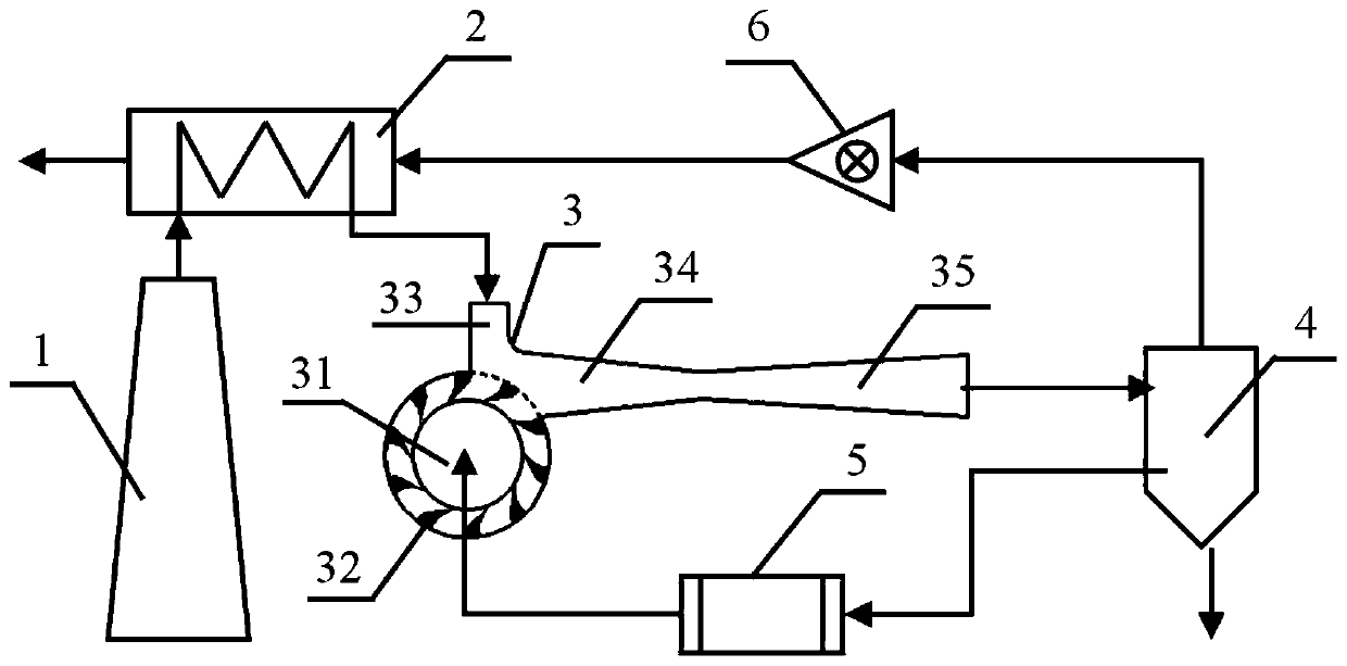
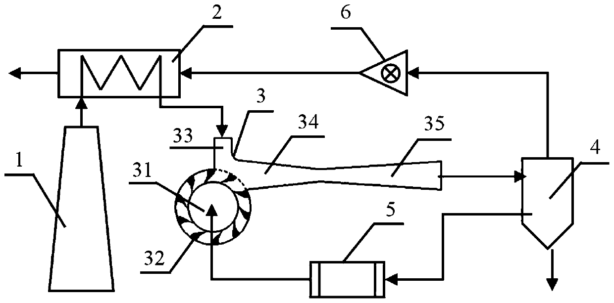
The invention discloses a device and a method for flue gas desulfurization in a thermal power plant. The device includes a chimney, a regenerative heat exchanger, a self-priming pulse jet desulfurizer, a separation tower, a slurry regulating system and an induced draft fan. The chimney communicates with the regenerative heat exchanger. The regenerative heat exchanger is connected to the separationtower through the self-priming pulse jet desulfurizer. The separation tower communicates with the self-priming pulse jet desulfurizer through the slurry regulating system. The separation tower communicates with the regenerative heat exchanger through the induced draft fan. The device and the method for flue gas desulfurization in a thermal power plant has the following beneficial effects: complexequipment for flue gas extraction, slurry mixing and the like in a typical desulfurization process is realized by a set of equipment, which makes the desulfurization process simpler and easier in popularization; and mixing methods which are most important in the desulfurization process are innovatively innovated, the conventional mixing methods such as spraying and mist spraying are converted into suction mixing, and an impeller is directly used to throw slurry out at high speed in a form of blocks part by part to form vacuum extraction flue gas, which realizes highly ordered mixing and improves the mixing efficiency.

Description

technical field [0001] The invention relates to the technical field of energy saving in thermal power plants, in particular to a device and method for flue gas desulfurization in thermal power plants. Background technique [0002] Flue gas desulfurization technology is currently recognized as the most effective technology for controlling sulfur dioxide pollution. The typical gypsum flue gas desulfurization technology is to use the limestone-containing slurry to wash the flue gas to neutralize the sulfur dioxide in the flue gas to achieve flue gas desulfurization emissions. The mixing degree and effect of flue gas and slurry directly affect the effect of flue gas desulfurization. In order to fully mix flue gas and slurry, the existing method uses an absorption tower for countercurrent mixing. The typical mixing process is: the limestone slurry is sprayed downward from the upper part of the tower and mixed with the flue gas flowing upwards in countercurrent. The sulfur dioxid...

Claims


Application Information

Patent Timeline
Patent Type & Authority Applications(China)
IPC IPC(8): B01D53/78B01D53/50
CPCB01D53/78B01D53/50
Inventor 张怀明
Owner WUHAN WU PUMP PUMP MFG
Learn More