
Finite element simulation modeling method suitable for longitudinal torsion ultrasonic milling

A simulation modeling and finite element technology, applied in design optimization/simulation, special data processing applications, instruments, etc., can solve the problems of long calculation time, complex model, inability to accurately reflect cutting force, etc., to achieve good economic benefits, easy to use. The effect of promotion

Active Publication Date: 2019-07-19
HENAN POLYTECHNIC UNIV
View PDF4 Cites 7 Cited by
  • Summary
  • Abstract
  • Description
  • Claims
  • Application Information

AI Technical Summary

Problems solved by technology

And it is impossible to simulate the ultrasonic vibration of the tool in the axial and torsional directions at the same time
[0008] (2) 3D model: the model is complex, the calculation takes a long time, and it has high requirements for computer hardware
[0009] (3) Three-dimensional simulation of longitudinal and torsional ultrasonic milling: Using traditional three-dimensional models, it is impossible to realize the simulation of simultaneous axial and torsional ultrasonic vibration of the tool
[0010] (4) Simulation of ultrasonic vibration milling cutting force: For the tool as the carrier of ultrasonic vibration, since ultrasonic vibration will generate high-frequency periodic acceleration, the traditional use of the reference point of the tool as the output particle of the cutting force cannot accurately reflect the actual cutting force

Method used


Image

  • Finite element simulation modeling method suitable for longitudinal torsion ultrasonic milling
  • Finite element simulation modeling method suitable for longitudinal torsion ultrasonic milling
  • Finite element simulation modeling method suitable for longitudinal torsion ultrasonic milling

Examples


Embodiment

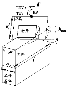
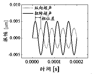
[0044] Example: see Figure 1-Figure 6 . A finite element simulation modeling method suitable for longitudinal torsion ultrasonic milling. Set the following parameters: milling cutter rake angle 5°, relief angle 12°, helix angle 30°, cutting edge radius 0.01mm, cutting speed 25m / min, per tooth Feed rate 0.008mm / z, radial depth of cut 0.15mm, axial depth of cut 2mm, longitudinal vibration amplitude 5μm, torsion amplitude 4μm, longitudinal torsion frequency 35kHz, longitudinal torsion phase difference 90°, tool material parameters are shown in Table 1. , The workpiece material parameters are shown in Tables 2 and 3, and the workpiece material unit failure criterion parameters are shown in Table 4.

[0045] Table 1 Tool material parameters

[0046]

[0047] Table 2 Workpiece material parameters

[0048]

[0049] Table 3 Constitutive parameters of workpiece material

[0050]

[0051] Table 4 Parameters of unit failure criterion of workpiece material

[0052]

[0053] According to the de...


PUM


Abstract

The invention discloses a finite element simulation modeling method suitable for longitudinal and torsional ultrasonic milling. The finite element simulation modeling method comprises the following steps of setting geometric parameters of a milling cutter, material parameters of a workpiece, material parameters of the milling cutter, machining process parameters and ultrasonic vibration parameters; converting the milling model, and establishing a longitudinal-torsional ultrasonic milling three-dimensional equivalent model; establishing a cutter, a workpiece, a workpiece base body and an assembly three-dimensional model; dividing grids for the cutter, the workpiece and the workpiece bse body; realizing longitudinal and torsional ultrasonic vibration of the cutter; setting cutter cutting motion boundary conditions; submitting calculation, and outputting the calculation results of the cutting edge movement track, the cutting force and the cutting temperature. According to the method, themilling model is converted, the milling three-dimensional finite element simulation of the tool serving as a longitudinal-torsional ultrasonic vibration carrier is successfully achieved, the spiral angle and the cutting edge radius of the tool are considered, the model and the actual machining process are more appropriate, and the calculation precision is guaranteed. Meanwhile, by establishing theworkpiece base body model, the output of the cutting force is realized.

Description

[0001] Technical field: [0002] The invention relates to an ultrasonic vibration machining modeling method, in particular to a finite element simulation modeling method suitable for longitudinal torsion ultrasonic milling. [0003] Background technique: [0004] Ultrasonic vibration, especially the two-dimensional longitudinal torsional ultrasonic vibration technology, can effectively reduce the average cutting force and cutting temperature during processing due to its high-frequency vibration impact and separation characteristics, and has an important position in anti-fatigue manufacturing technology. The combination of ultrasonic technology and milling processing methods to obtain active control of the processed surface compressive stress is one of the main methods of fatigue-resistant manufacturing technology research in the field of mechanical manufacturing. [0005] With the continuous improvement of computer hardware level, it is an effective method to simulate ultrasonic millin...

Claims


Application Information

Patent Timeline
IPC IPC(8): G06F17/50
CPCG06F30/17G06F30/23
Inventor 牛赢赵波焦锋童景琳马俊金牛晶晶
Owner HENAN POLYTECHNIC UNIV
Learn More