
Barrier gate machine core device with efficient transmission and high adjustability

An adjustable and high-efficiency technology, applied in roads, roads, restricted traffic and other directions, can solve the problems of large jitter of the brake lever, high cost, and affecting the life of the motor, so as to improve the efficiency of force transmission, small movement gap and long life. Effect

Pending Publication Date: 2019-07-19
JIDA JOINT PRECISION MACHINERY XIAMEN CO LTD
View PDF0 Cites 2 Cited by
  • Summary
  • Abstract
  • Description
  • Claims
  • Application Information

AI Technical Summary

Problems solved by technology

The disadvantages of the existing four-bar mechanism in the barrier gate industry are mainly due to the fact that the swing angle of the rocker is 90 degrees during work, and the transmission angle between the connecting rod and the rocker changes greatly, which makes the transmission efficiency of the mechanism low and causes a large impact on the frame. impact, resulting in greater jitter of the brake lever and affecting the life of the motor; the direct drive of the motor generally uses a servo or frequency converter to control the speed of the motor, and the cost is relatively high

Method used


Image

  • Barrier gate machine core device with efficient transmission and high adjustability
  • Barrier gate machine core device with efficient transmission and high adjustability
  • Barrier gate machine core device with efficient transmission and high adjustability

Examples


Embodiment Construction

[0017] The present invention will be described in further detail below in conjunction with the accompanying drawings and specific embodiments.

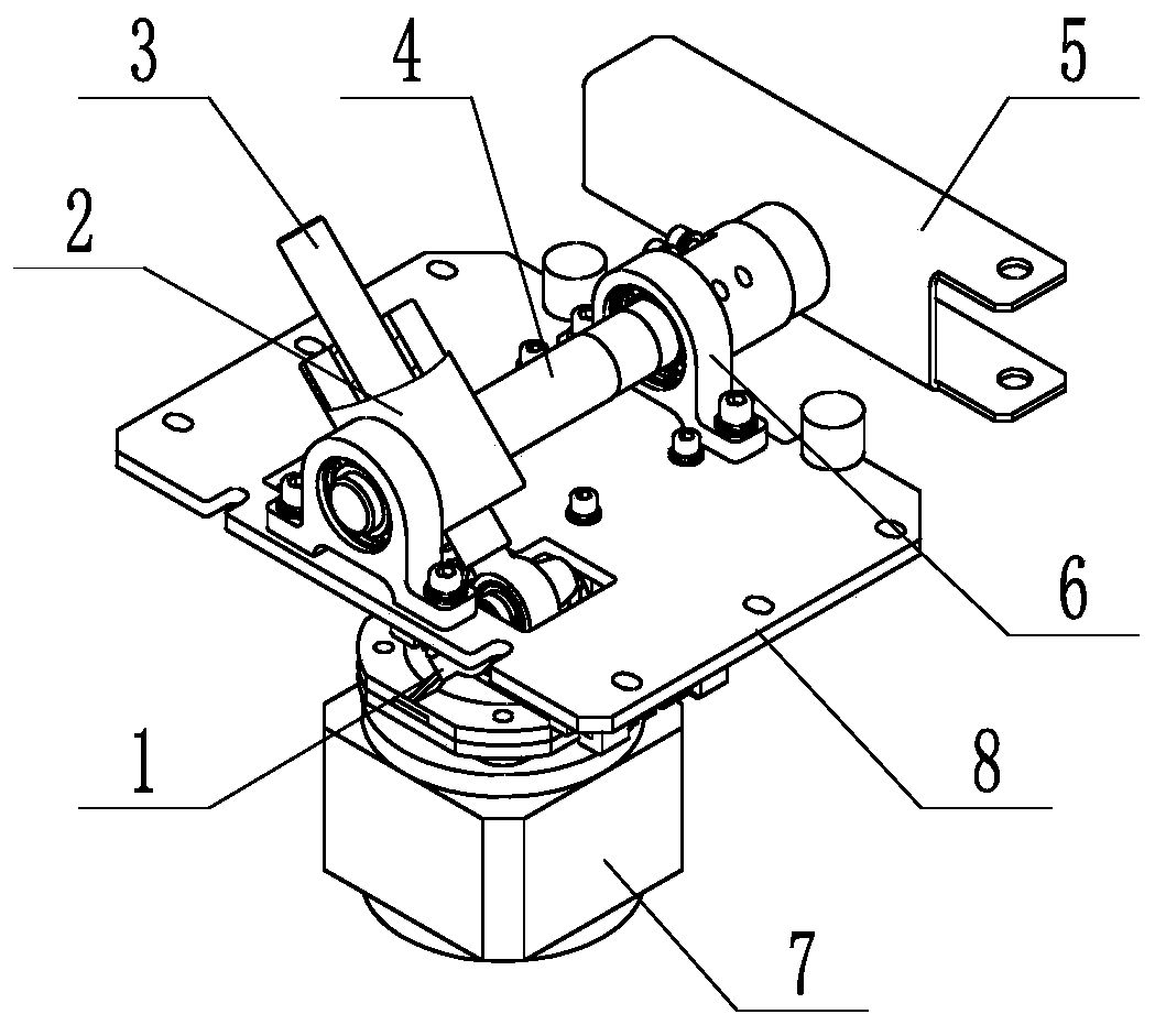
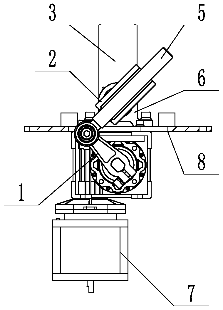
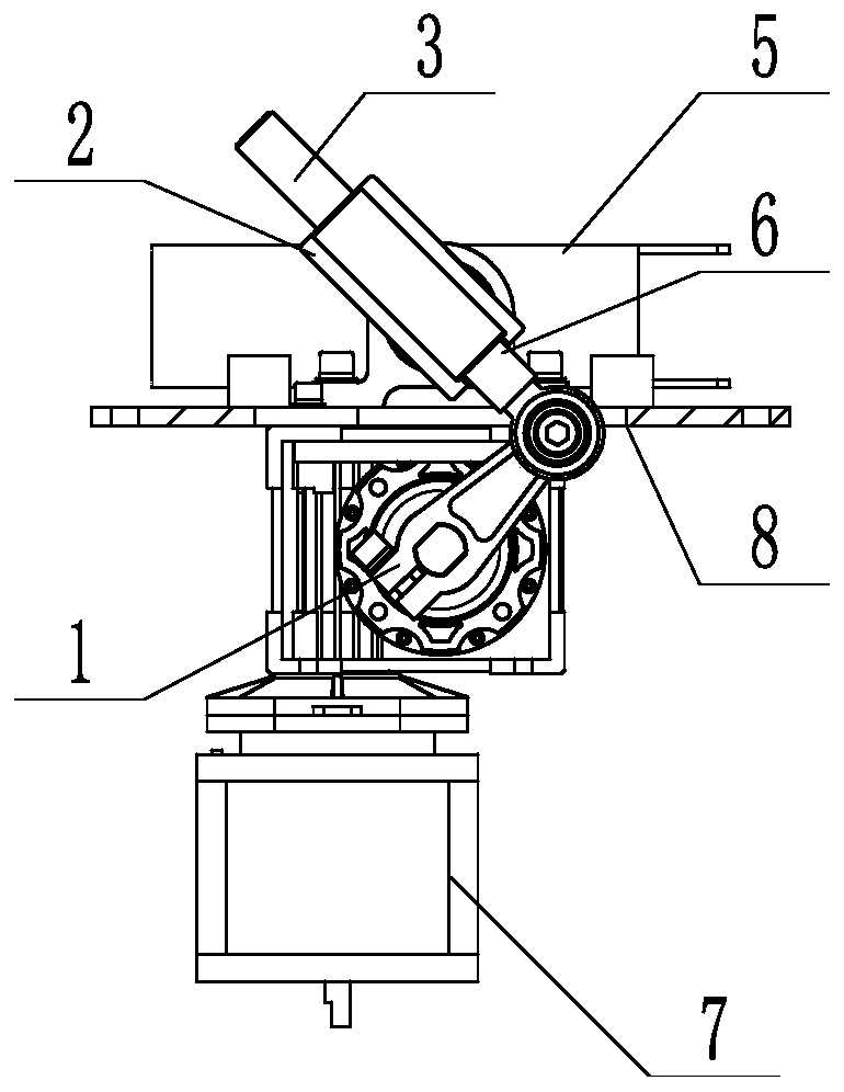
[0018] Such as figure 1 As shown, a barrier gate movement device with high transmission efficiency and high adjustability includes a motor crank 1, a guide rod 3, and a transmission spindle 4. The first end of the motor crank 1 is fixedly connected to the output shaft of the geared motor. The second end of the motor crank 1 is hinged to the guide rod 3, and the transmission main shaft 4 includes a first shaft portion and a second shaft portion on the same rotation center line, and a shaft is provided between the first shaft portion and the second shaft portion The slider support 2, the first shaft part and the second shaft part are installed on the frame 8 through the bearing housing 6 respectively, the guide rod 3 is slidingly connected with the slider support 3, the motor crank 1 rotates and Drive the guide rod 3 to swing, and the ...


PUM


Abstract

The invention relates to a barrier gate machine core device with efficient transmission and high adjustability. The barrier gate machine core device comprises a motor crank, a guiding rod and a transmission main shaft; and the first end of the motor crank is fixedly connected with an output shaft of a speed reducing motor, the second end of the motor crank is hinged to the guiding rod, the transmission main shaft comprises a first shaft part and a second shaft part, a sliding block supporting seat is arranged between the first shaft part and the second shaft part, the guiding rod is slidably connected with the sliding block supporting seat, the motor crank rotates and drives the guiding rod to swing, the guiding rod drives the sliding block supporting seat to push the transmission main shaft to swing between the first limit position and the second limit position, and a gate rod is connected with the transmission main shaft to realize swing between the horizontal direction and the vertical direction. According to the barrier gate machine core device, the force transferring efficiency of a barrier gate machine core and the stability of a rack can be improved, the motion gap is small,the life of a speed reducer is obviously prolonged, the cost is low, thus the production cost of a barrier gate is finally lowered, the using stability of a barrier gate machine is improved, and thelife of the barrier gate machine is prolonged.

Description

technical field [0001] The invention relates to a parking lot and a road barrier, in particular to a barrier gate movement device with high transmission efficiency and high adjustability. Background technique [0002] At present, in the barrier gate industry, the transmission device of the gate movement is generally in the form of a four-bar linkage mechanism or a direct drive of a motor. The disadvantages of the existing four-bar mechanism in the barrier gate industry are mainly due to the fact that the swing angle of the rocker is 90 degrees during work, and the transmission angle between the connecting rod and the rocker changes greatly, which makes the transmission efficiency of the mechanism low and causes a large impact on the frame. The impact of the brake lever will cause greater vibration and affect the life of the motor; the direct drive of the motor generally uses a servo or frequency converter to control the speed of the motor, and the cost is relatively high. ...

Claims


Application Information

Patent Timeline
IPC IPC(8): E01F13/06
CPCE01F13/06
Inventor 陆勇陈宏伟石欣鹏
Owner JIDA JOINT PRECISION MACHINERY XIAMEN CO LTD
Learn More