
An easy-to-detach tail structure with adjustable installation angle

An adjustable installation angle technology, applied in transportation and packaging, aircraft stability, fuselage, etc., can solve the problems of inability to deal with longitudinal trim, complex installation angle adjustment mechanism, and less reliable than fixed connection, etc., to achieve small footprint , light weight, quick disassembly effect

Active Publication Date: 2021-01-12
BEIHANG UNIV
View PDF7 Cites 0 Cited by
  • Summary
  • Abstract
  • Description
  • Claims
  • Application Information

AI Technical Summary

Problems solved by technology

[0003] Existing tail structures of small and medium-sized UAVs are often designed in the form of fixed connection or real-time adjustable installation angle. The former cannot adjust the installation angle and cannot cope with the longitudinal trim problem that may occur during flight tests; the latter has a more complicated installation angle adjustment mechanism. The weight gain is large and the reliability is far inferior to the fixed connection method, which can only be applied to large aircraft (such as large passenger aircraft or transport aircraft, etc.)

Method used


Image

  • An easy-to-detach tail structure with adjustable installation angle
  • An easy-to-detach tail structure with adjustable installation angle
  • An easy-to-detach tail structure with adjustable installation angle

Examples


Embodiment Construction

[0025] The present invention will be described in further detail below in conjunction with the accompanying drawings.

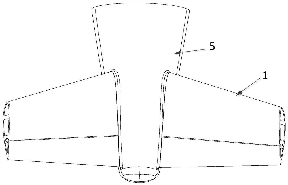
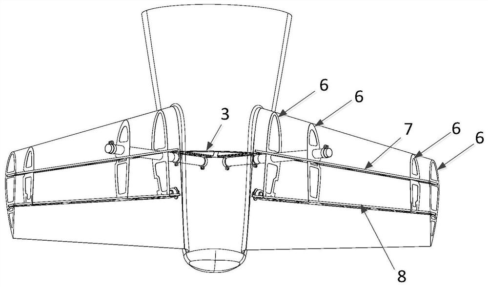
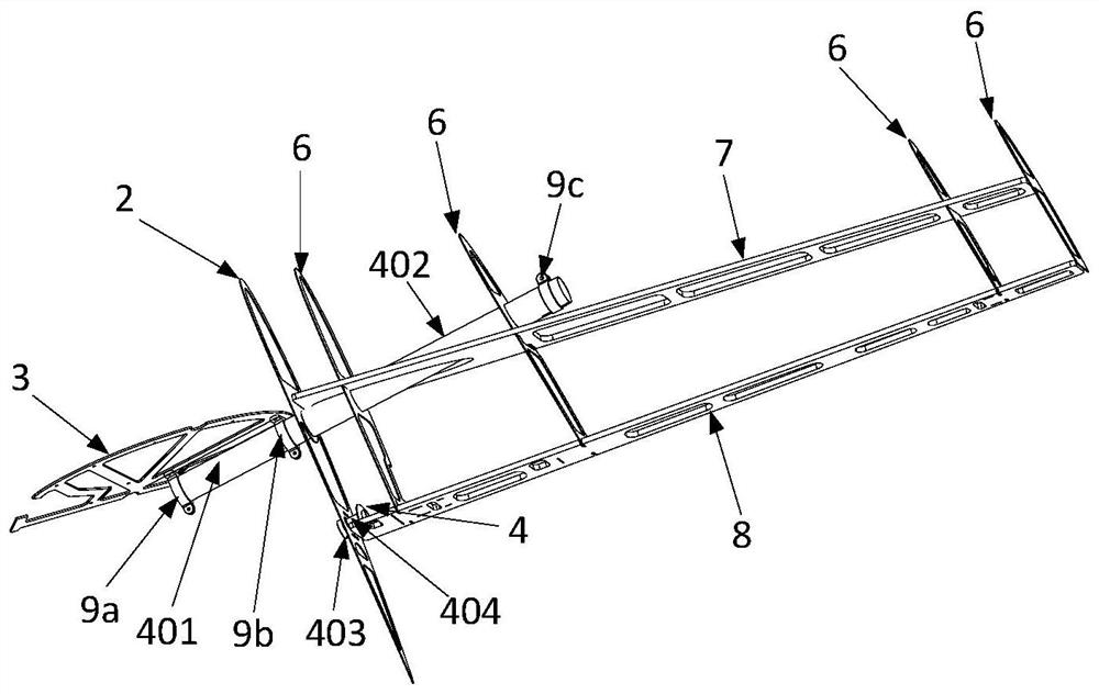
[0026] The easy-to-detachable empennage structure with adjustable installation angle of the present invention includes an empennage 1, an installation plate 2, a fuselage frame 3 and an empennage installation angle adjustment mechanism 4, and can be applied to flat-tail UAVs with V-shaped, cross-shaped or T-shaped empennages ,Such as figure 1 , 2 , 3 shown.

[0027] The empennage 1 is located on both sides of the rear end of the fuselage 5 and has a V-shaped structure. The empennage 1 has wing ribs 6 inside, and the front and rear parts of the empennage 1 have empennage front beams 7 and empennage rear beams 8 . The empennage 1 root is installed at the mounting opening on the fuselage 5 side walls, and the mounting plate 2 with the same longitudinal section shape as the empennage 1 root is fitted. The fuselage partition frame 3 is installed inside the fus...


PUM


Abstract

The invention discloses an easy-to-detach empennage structure adjustable in mounting angle. Empennage front beams and empennage rear beams are fixedly connected with front beam rotary casing pipes andrear beam rotary casing pipes in a bonding mode, turning of a power transmission line is realized, and empennages achieve the capability of changing the mounting angle. The front beam rotary casing pipes which are fixedly connected with the front beams are fixed to front beam fixed shafts fixed to a fuselage bulkhead, and the rear beam rotary casing pipes which are fixedly connected with the rearbeams are fixed to rear beam fixed shafts fixed to movable bases. When the mounting angle needs to be adjusted, only aluminum hoops fixing the front beam rotary casing pipes and screws fixing the rear beam movable bases need to be loosened, the empennages are rotated around front beam rotation shafts at a specified angle, and then the aluminum hoops and the screws are tightened so that adjustmentof the mounting angle can be completed. According to the empennage structure, on the premise of ensuring the strength of the empennage structure, the empennages can be detached very conveniently, andthe mounting angle of the empennages can be adjusted very conveniently so that an aircraft can meet different longitudinal trimming requirements, and the risk and cost of aircraft development at theinitial stage are reduced.

Description

technical field [0001] The invention belongs to the field of aircraft design, and relates to an empennage structure, specifically, an empennage structure capable of adjusting the installation angle and quickly disassembling. Background technique [0002] During the flight of a conventional layout aircraft, the empennage plays an important role in balancing the force on the whole aircraft and controlling the movement of the aircraft. Among them, the V-shaped tail can simultaneously stabilize and control the pitch and yaw directions. In the early stage of the development of small and medium-sized UAVs, due to the needs of flight tests, it is often required that the installation angle of the tail can be adjusted to deal with temporary problems such as insufficient take-off torque and insufficient longitudinal trim capabilities during the flight test phase of the aircraft. [0003] Existing tail structures of small and medium-sized UAVs are often designed in the form of fixed c...

Claims


Application Information

Patent Timeline
Patent Type & Authority Patents(China)
IPC IPC(8): B64C5/00B64C1/26
Inventor 马东立姚远胡浩德陈锦涌罗智刚
Owner BEIHANG UNIV
Learn More