
Knife flywheel grinding device

A grinding and cutter wheel technology, which is applied in the direction of grinding drive device, grinding/polishing safety device, grinding frame, etc., can solve the problems of low yield rate and human error, so as to ensure the yield rate and accuracy , The effect of eliminating the error

Pending Publication Date: 2019-07-19
深圳市威雄精机有限公司
View PDF0 Cites 0 Cited by
  • Summary
  • Abstract
  • Description
  • Claims
  • Application Information

AI Technical Summary

Problems solved by technology

[0003] The purpose of the present invention is to provide a cutter wheel grinding device, aiming to solve the problem that the cutter wheel grinding device in the prior art needs to manually adjust the installation structure during the grinding process, and the movement of the super-grinding structure will cause human errors, resulting in defective products. low rate technical issues

Method used


Image

  • Knife flywheel grinding device
  • Knife flywheel grinding device
  • Knife flywheel grinding device

Examples


Embodiment Construction

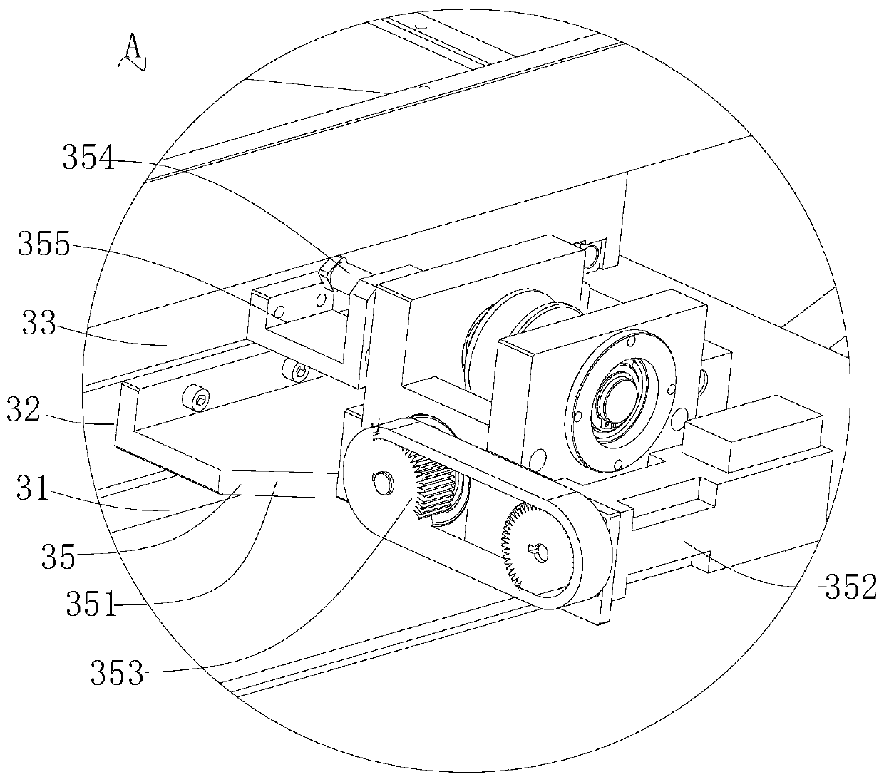
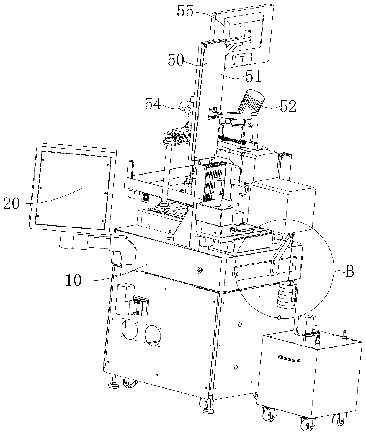
[0035] Embodiments of the present invention are described in detail below, examples of which are shown in the drawings, wherein the same or similar reference numerals designate the same or similar elements or elements having the same or similar functions throughout. Attached below by reference Figure 1~6 The described embodiments are exemplary and are intended to explain the present invention, but should not be construed as limiting the present invention.

[0036] In describing the present invention, it should be understood that the terms "length", "width", "upper", "lower", "front", "rear", "left", "right", "vertical", The orientation or positional relationship indicated by "horizontal", "top", "bottom", "inner", "outer", etc. are based on the orientation or positional relationship shown in the drawings, and are only for the convenience of describing the present invention and simplifying the description, rather than Nothing indicating or implying that a referenced device or...


PUM


Abstract

The invention belongs to the technical field of knife flywheel grinding, and particularly relates to a knife flywheel grinding device. The device is characterized in that a mounting assembly comprisesa first sliding platform, a second sliding platform and a mounting positioning structure, wherein a knife flywheel is arranged on the mounting positioning structure; the first sliding platform can slide on a mounting seat and is capable of sliding the knife flywheel on the mounting positioning structure in a wide range, thus the mounting positioning structure is close to a grinding assembly; thesecond sliding platform is arranged, and a sliding control structure is arranged between the second sliding platform and the first sliding platform, so that the second sliding platform can be controlled to slide on the first sliding platform through a control assembly; in addition, the sliding distance of the second sliding platform can be accurately controlled through the control assembly, so that the error of the knife flywheel grinding size and the preset size is reduced. Therefore, the sliding control structure can be automatically controlled through the control assembly so as to ensure the feeding and returning distance accuracy, and as a result, the error of manual operation is removed, and the yield of the grinded knife flywheel can be ensured.

Description

technical field [0001] The invention belongs to the technical field of cutter wheel grinding, and in particular relates to a cutter wheel grinding device. Background technique [0002] The existing cutter wheel grinding devices all include a mounting structure for installing the cutter wheel and a grinding structure for grinding the cutter wheel. In order to control the shape and size of the cutter wheel, the mounting structure can slide back and forth toward the grinding structure, but The fine-tuning of the existing installation structure is achieved through the handwheel plus the worm gear and the screw nut. Generally, the handwheel rotates 6°, and the fine-tuning feed or retreat distance is 1μm, but manual adjustment of the rotation of the handwheel will be caused by human error. The yield rate is low, and manual adjustment of tight instruments will reduce work efficiency. Contents of the invention [0003] The purpose of the present invention is to provide a cutter w...

Claims


Application Information

Patent Timeline
Patent Type & Authority Applications(China)
IPC IPC(8): B24B47/20B24B41/06B24B3/46B24B55/00B24B41/02B24B47/06B24B49/00
CPCB24B47/20B24B41/06B24B3/46B24B55/00B24B41/02B24B47/06B24B49/00
Inventor 叶民崇易钢杨胡振华黄伟王小东
Owner 深圳市威雄精机有限公司
Learn More