Composite vacuum deposition method of composite magnetic field, composite tube and porous baffle

A porous baffle and vacuum deposition technology, applied in vacuum evaporation coating, ion implantation coating, metal material coating process, etc., can solve the problem of unstable discharge of high-power pulsed magnetron sputtering and low transmission efficiency of arc plasma , low film deposition efficiency, etc., to achieve the effect of easy disassembly and assembly and cleaning of pollutants, avoiding pollution of the inner wall of the tube, and avoiding difficult cleaning.

Pending Publication Date: 2019-07-09
魏永强
View PDF9 Cites 0 Cited by
  • Summary
  • Abstract
  • Description
  • Claims
  • Application Information

AI Technical Summary

Problems solved by technology

[0006] The purpose of the present invention is to solve the problem of low ionization rate and thin film deposition efficiency of traditional magnetron sputtering technology, the limitation of high melting point target material use, and the current high-power pulse magnetron sputtering. The plating method uses high melting point targets, low melting point pure metals (such as aluminum, tin) or multi-element alloy materials (such as AlSi alloys) and non-metallic materials (such as graphite and semiconductor materials Si) as targets that are prone to large particle defects, bending Low efficiency of arc plasma transmission caused by type magnetic filter technology, limitation of target element usage and uniform ablation, thin film deposition density and defects, deposition position limitation caused by vacuum chamber space and target source layout design, workpiece shape limitation and different target In order to solve problems such as contamination of film components caused by secondary sputtering of residues in multi-level magnetic field devices, pure metals with low melting points (such as aluminum, tin) or multi-element alloy materials (such as AlSi alloys) and non-metallic materials (such as graphite and Semiconductor material Si, etc.) as the target material of high-power pulsed magnetron sputtering, and then use the arc ion plating method to realize the high melting point refractory target material to produce continuous and stable plasma with high ionization rate, combined with multi-level magnetic field filtering method and The shape constraints of the lined bias conical tube, straight tube and porous baffle combined device and the combined effect of bias electric field attraction can eliminate the large particle defects contained in the arc plasma, and at the same time ensure that the arc plasma has a high The transmission efficiency is eliminated from the multi-level magnetic field through the combination of the lined bias conical tube, the straight tube and the porous baffle device and the multi-stage magnetic field filter device, and then using the combined effect of the magnetic field confinement of the movable coil device and the self-bias electric field attraction. The large particle defects contained in the arc plasma transmitted by the device and the liner bias conical tube, straight tube and porous baffle device, while using the movable coil device to control the combination of high-power pulse magnetron sputtering and arc ion plating The transmission direction of the plasma in the vacuum chamber realizes the control and adjustment of the film deposition and film composition on the surface of the substrate workpiece at any position in the vacuum chamber, reduces the loss of the composite plasma in the vacuum chamber, and overcomes the limitations of the vacuum chamber and the target source position or the substrate. The non-uniform film deposition problem caused by shape limitation, completely remove the large particle defects that may remain in the arc plasma transmitted from the multi-level magnetic field device and the lined bias conical tube, straight tube and porous baffle combination device, Make the surface of the workpiece adjust the ion energy under the condition of applying a negative bias voltage, use the bias electric field suppression effect on the surface of the substrate to remove large particle defects in the arc plasma, prepare continuous, dense and high-quality films, and at the same time realize the target material in the film Adding control of element content, reducing the production cost of using alloy targets, improving the transmission efficiency of plasma, increasing the deposition rate of thin films and reducing or even eliminating the adverse effects of large particle defects on thin film microstructure, continuous dense deposition and service performance, a new method is proposed. A composite vacuum deposition method of combined magnetic field, combined tube and porous baffle

Method used


Image

  • Composite vacuum deposition method of composite magnetic field, composite tube and porous baffle
  • Composite vacuum deposition method of composite magnetic field, composite tube and porous baffle
  • Composite vacuum deposition method of composite magnetic field, composite tube and porous baffle

Examples


specific Embodiment approach 1

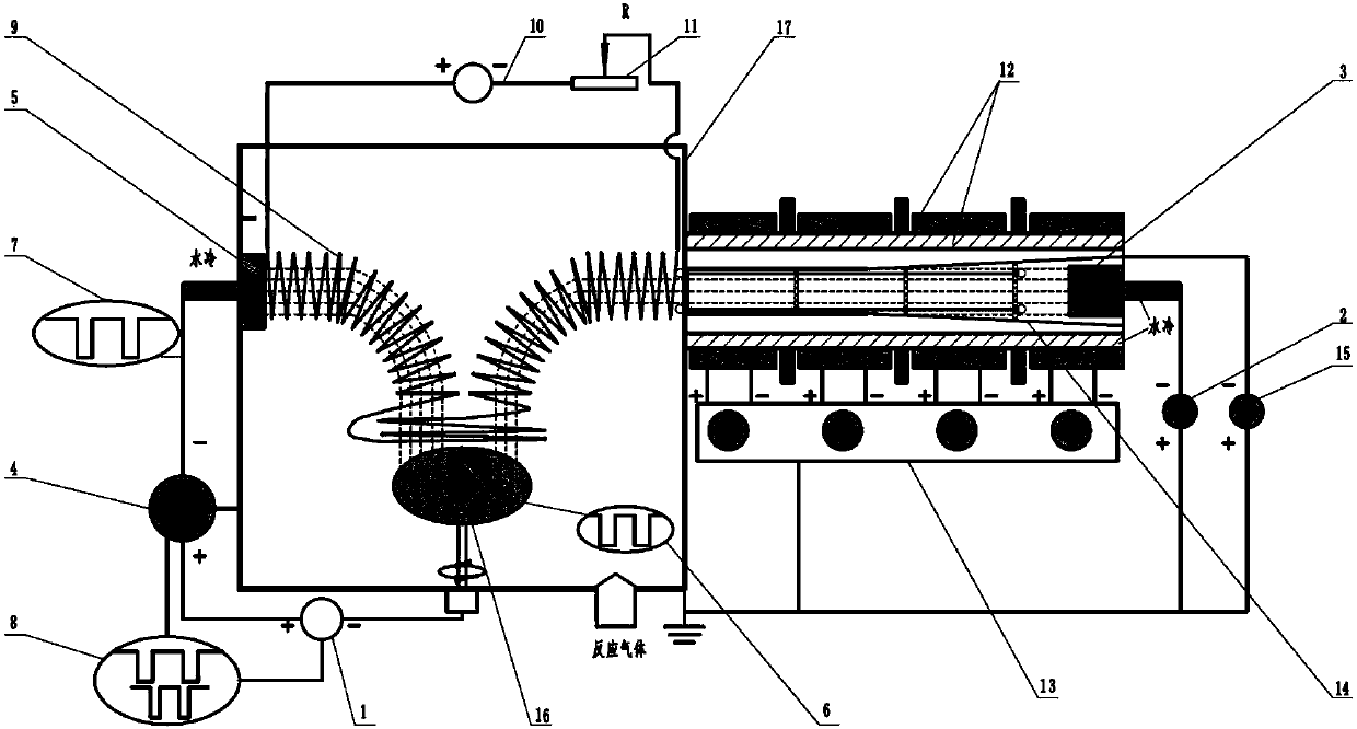
[0025] Specific implementation mode one: the following combination Figure 1-4 Describe this embodiment, the device used in this embodiment is a combination of magnetic field, combined tube and porous baffle combined vacuum deposition method includes bias power supply (1), arc power supply (2), arc ion plating target source (3), High-power pulsed magnetron sputtering power supply (4), high-power pulsed magnetron sputtering target source (5), bias power waveform oscilloscope (6), high-power pulsed magnetron sputtering power supply waveform oscilloscope (7), waveform synchronization Matching device (8), movable coil device (9), movable coil device power supply (10), rheostat device (11), multi-stage magnetic field device (12), multi-stage magnetic field device power supply (13), lining bias cone Tube, straight tube and porous baffle combined device (14), lining bias power supply (15), sample stage (16) and vacuum chamber (17);

[0026] In this device:

[0027]The workpiece to ...

specific Embodiment approach 2

[0044] Embodiment 2: The difference between this embodiment and Embodiment 1 is that a combined vacuum deposition method of combined magnetic field, combined tube and porous baffle is connected, the arc power supply (2) is turned on, and the multi-stage magnetic field power supply (5 ) adjust the multi-stage magnetic field device (12), turn on the liner bias power supply (15), adjust the bias voltage of the liner bias conical tube, straight tube and porous baffle combination device (14), turn on the movable coil device power supply (10 ) adjust the movable coil device (9), adjust the output resistance of the rheostat device (10), and control the bias power supply (1) and the high-power pulse magnetron sputtering power supply (4) to be turned on simultaneously by the waveform synchronous matching device (8). The period of the output pulse of the power pulse magnetron sputtering power supply (4) is an integer multiple of the output pulse of the bias power supply (1), such as Fi...

specific Embodiment approach 3

[0045] Embodiment 3: The difference between this embodiment and Embodiment 1 is that a vacuum deposition method combining a combined magnetic field, a combined tube and a porous baffle is connected, the arc power supply (2) is turned on, and the multi-stage magnetic field power supply (5 ) adjust the multi-stage magnetic field device (12), turn on the liner bias power supply (15), adjust the bias voltage of the liner bias conical tube, straight tube and porous baffle combination device (14), turn on the movable coil device power supply (10 ) adjust the movable coil device (9), adjust the output resistance of the rheostat device (10), and control the bias power supply (1) and the high-power pulse magnetron sputtering power supply (4) to be turned on simultaneously by the waveform synchronous matching device (8). Power pulse magnetron sputtering power supply (4) outputs high-power pulses and bias voltage pulse waveform output by bias power supply (1) is adjustable in phase, such ...


PUM


Abstract

The invention discloses a composite vacuum deposition method of a composite magnetic field, a composite tube and a porous baffle, and belongs to the technical field of material surface treatment. Theproblems of contamination of thin films and target material usage restrictions by large particles, loss of magnetically filtered arc plasma, and instability of high power pulsed magnetron sputtering discharge in arc ion plating are solved. A device comprises a target source of arc ion plating, a multistage magnetic field device, a lined bias voltage tapered tube, a straight tube and porous bafflecomposite device, a high power pulse magnetron sputtering target source, a movable coil device, a relevant power supply, a bias voltage power supply, a waveform matching device, and other devices; andthin film deposition is conducted, specifically, the device is connected, a system is started, working gas is injected when the vacuum degree in a vacuum chamber is less than 10<-4> Pa, a plating power supply is turned on, the bias voltage power supply regulates energy of plasma, the multistage magnetic field device and the movable coil device eliminate large particle defects and guide transmission of composite plasma, the loss in the vacuum chamber is reduced, and technological parameters are set.

Description

technical field [0001] The invention relates to a composite vacuum deposition method of combined magnetic field, combined tube and porous baffle, and belongs to the technical field of material surface treatment. Background technique [0002] In the process of preparing thin films by arc ion plating, due to the arc spot current density as high as 2.5~5×10 10 A / m 2 , causing molten liquid metal to appear at the arc spot position on the target surface, which is splashed out in the form of droplets under the action of local plasma pressure, and adheres to the surface of the film or is embedded in the film to form "macroparticles" (Macroparticles) Defects (BoxmanR L, Goldsmith S. Macroparticle contamination in cathodic arc coatings: generation, transport and control [J]. Surf Coat Tech, 1992, 52(1): 39-50.). In the arc plasma, since the movement speed of electrons is much greater than that of ions, the number of electrons reaching the surface of large particles per unit time is...

Claims


Application Information

Patent Timeline
IPC IPC(8): C23C14/35C23C14/34
CPCC23C14/3407C23C14/3485C23C14/3492C23C14/35
Inventor 魏永强王好平宗晓亚张新国刘学申蒋志强
Owner 魏永强
Why Eureka
Try Eureka