
SOI device structure

A device and high-voltage device technology, applied in the field of SOI device structure, can solve the problems of ignoring the improvement of the field oxide layer and the influence of heat dissipation cannot be ignored

Inactive Publication Date: 2019-07-05
上海卓弘微系统科技有限公司 +2
View PDF0 Cites 0 Cited by
  • Summary
  • Abstract
  • Description
  • Claims
  • Application Information

AI Technical Summary

Problems solved by technology

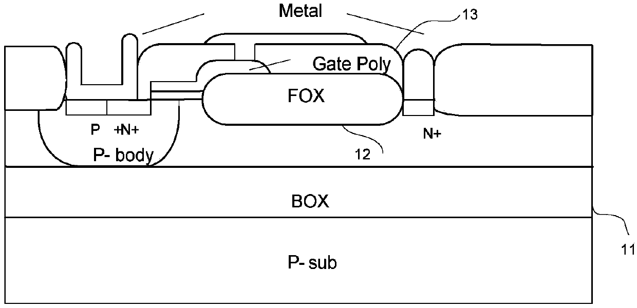
[0003] Since the SOI structure is based on the bulk silicon process, an additional buried oxide layer 11 is added, which greatly reduces the heat dissipated from the substrate. Therefore, most papers and patents discuss how to change the structure and material of the buried layer to achieve It is beneficial to heat dissipation, thus ignoring the improvement of the field oxide layer 12, especially for high-voltage devices, the thickness of the field oxide layer is similar to the thickness of the buried layer, and the thickness of the superimposed oxide layer such as the isolation layer 13 makes the former’s influence on heat dissipation even less. neglect

Method used


Image

  • SOI device structure
  • SOI device structure
  • SOI device structure

Examples


Embodiment Construction

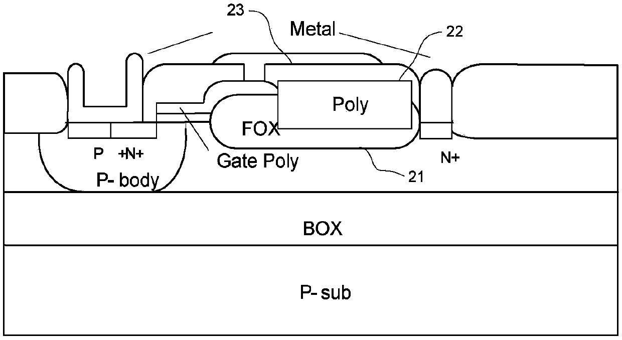
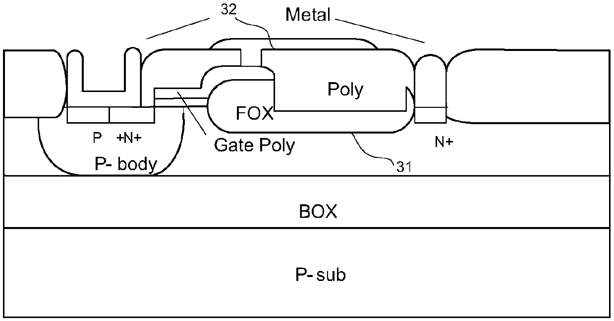
[0015] figure 2 It is a schematic diagram of the SOI-LDMOS structure in the first embodiment of the present invention. This structure changes the material of the field oxide layer 21 into an undoped POLY material. After the field oxide layer grows, part of it is etched away, and POLY22 is deposited. An isolation oxide layer 23 is then deposited, and finally a metal electrode is deposited. Due to SiO 2 The thermal conductivity of Si is about 1 / 100, but the dielectric constant is 3 times that of Si, so this change can greatly reduce the thermal resistance of the field oxygen part, which is conducive to heat dissipation, while the thermal resistance of the field oxide layer and the buried layer The thermal resistance is equivalent to a parallel relationship, and the significantly lower thermal resistance of the field oxide layer will cause most of the heat to be lost from the field oxide layer, which can achieve the purpose of effective heat dissipation.

[0016] image 3 It ...


PUM


Abstract

The present invention discloses a semiconductor SOI (Silicon-On-Insulator) high-voltage device structure and manufacturing method thereof which can improve the heat dissipation performance. The SOI device structure with a good heat dissipation performance comprises a material configured to change a high-voltage SOI device field oxide layer so that the heat dissipation performance of the SOI high-voltage device can be effectively improved by employing the difference of thermal conductivities and the dielectric constants of different materials and without change of the device size and change ofthe three-layer structure portions of the SOI.

Description

technical field [0001] The invention relates to the field of semiconductor SOI high-voltage devices, in particular to an SOI device structure with better heat dissipation performance. Background technique [0002] SOI (Silicon-On-Insulator, silicon on insulating substrate) technology introduces a buried oxide layer between the top silicon and the back substrate. By forming a semiconductor thin film on an insulator, the SOI material has the incomparable advantages of bulk silicon: it can realize the dielectric isolation of components in integrated circuits, and completely eliminate the parasitic latch effect in bulk silicon CMOS circuits; The integrated circuit also has the advantages of small parasitic capacitance, high integration density, fast speed, simple process, small short channel effect, and is especially suitable for low-voltage and low-power circuits. Therefore, it can be said that SOI will likely become a deep submicron low-voltage , the mainstream technology of ...

Claims


Application Information

Patent Timeline
Patent Type & Authority Applications(China)
IPC IPC(8): H01L21/762H01L23/373
CPCH01L21/76286H01L23/3738
Inventor 沈立陆宇周润宝沈金龙程玉华
Owner 上海卓弘微系统科技有限公司
Learn More