Self-cooling type cooling water pump for engine

A technology for cooling water pumps and engines, which is applied in the cooling of engines, engine components, machines/engines, etc., can solve the problems of limiting the continuous working time and speed of the water pump, the influence of the service life of the water pump, and the use of the water pump, so as to improve the energy utilization rate. , the effect of improving cooling efficiency and improving heat dissipation efficiency

Pending Publication Date: 2019-07-05
DAFENG HAINA MACHINERY
View PDF0 Cites 2 Cited by
  • Summary
  • Abstract
  • Description
  • Claims
  • Application Information

AI Technical Summary

Problems solved by technology

[0003] During the working process of the cooling water pump, the rotation of the bearing and the pump shaft generates heat. Since the bearing is located inside the pump body, it is difficult to dissipate the heat to the pump body, which limits the continuous working time and speed of the water pump and affects the use of the pump. At the same time, it will also affect the service life of the pump

Method used


Image

  • Self-cooling type cooling water pump for engine
  • Self-cooling type cooling water pump for engine
  • Self-cooling type cooling water pump for engine

Examples


Embodiment 1

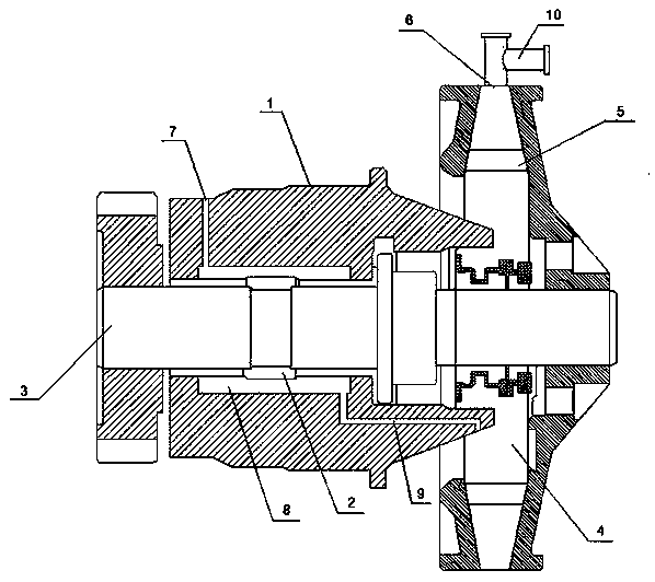
[0022] Embodiment 1: This embodiment provides a self-cooling engine cooling water pump, including a pump housing 1, the right end of the pump housing 1 is provided with an impeller 5 cavity 4, a bearing 2 is installed in the pump housing 1, and the bearing 2 rotates The pump shaft 3 is installed, the right end of the pump shaft 3 is equipped with an impeller 5, the impeller 5 is located in the chamber 4 of the impeller 5, the left end of the pump shaft 3 extends outside the pump casing 1 and is connected with the gear, which is connected with the engine for transmission and works At this time, the engine drives the pump shaft 3 to rotate through the gear, thereby driving the impeller 5 to rotate in the cavity 4 of the impeller 5 .

[0023] A liquid inlet 6 and a liquid outlet 7 are opened on the pump casing 1, and a cooling chamber 8 is opened in the pump casing 1, see figure 1 , the cooling chamber 8 is a hollow cylinder and covers the outside of the bearing 2. The length of ...

Embodiment 2

[0027] Embodiment 2: This embodiment provides a cooling water pump for a self-cooling engine. The difference from Embodiment 1 is that the cooling chamber 8 in this embodiment is a spiral pipe wound outside the bearing 2. See figure 2 , the spiral pipe completely covers the outer surface of the bearing 2, the coolant in the cavity 4 of the impeller 5 enters from one end of the spiral pipe, then flows along the pipe and is transported to the liquid outlet 7 on the pump casing 1 place, so that the spiral pipe is always filled with coolant, which ensures the coverage area of ​​the coolant and has higher heat absorption efficiency.


PUM


Abstract

The invention discloses a self-cooling type cooling water pump for an engine and relates to the technical field of water pumps. The self-cooling type cooling water pump for the engine comprises a pumpshell, wherein a bearing is arranged in the pump shell; a pump shaft is mounted in the bearing in a rotatable manner; an impeller cavity is formed in the pump shell; one end of the pump shaft is connected with an impeller located in the impeller cavity; the pump shell is provided with a liquid inlet and a liquid outlet; a cooling chamber is arranged in the pump shell; the cooling chamber covers the bearing; the pump shell is internally provided with a cooling liquid channel; one end of the cooling liquid channel communicates with the impeller cavity and the other end of the cooling liquid channel passes through the cooling chamber and is connected with the liquid outlet; and cooling liquid flows in the cooling chamber and heat generated on the bearing can be absorbed, so that the inner part of the pump shell is automatically cooled and the water pump can be continuously operated at a high speed.

Description

technical field [0001] The invention relates to the technical field of water pumps, in particular to a cooling water pump for a self-cooling engine. Background technique [0002] When the engine uses the cooling water pump to work, the engine drives the water pump bearing and the impeller to rotate through the pulley, and the coolant in the water pump is driven by the impeller to rotate together, and is thrown to the edge of the water pump shell under the action of centrifugal force, and a certain pressure is generated at the same time, and then from Out of a sewer or pipe. The pressure at the center of the impeller decreases due to the coolant being thrown out, and the coolant in the water tank is sucked into the impeller through the water pipe under the action of the pressure difference between the pump inlet and the center of the impeller to realize the reciprocating circulation of the coolant. [0003] During the working process of the cooling water pump, the rotation o...

Claims


Application Information

Patent Timeline
IPC IPC(8): F01P5/10F01P7/16F04D29/58F04D29/046B60H1/04
CPCF01P5/10F01P7/16F04D29/586F04D29/046B60H1/04
Inventor 王华生
Owner DAFENG HAINA MACHINERY
Why Eureka
Try Eureka