
Section steel-UHPC composite board and bridge deck

A technology of combining slabs and bridge decks, used in bridges, bridge parts, bridge construction, etc., can solve problems such as bridge deck cracking and reducing the dead weight of main beams

Pending Publication Date: 2019-07-05
HUNAN UNIV
View PDF0 Cites 4 Cited by
  • Summary
  • Abstract
  • Description
  • Claims
  • Application Information

AI Technical Summary

Problems solved by technology

For traditional composite girder cable-stayed bridges, the steel-UHPC composite deck can reduce the self-weight of the main girder and further increase the span of the composite girder cable-stayed bridge. The beams will still bear the tension, and the transverse connection between the decks of the main girders is a weak section, where there is still a risk of cracking of the decks

Method used


Image

  • Section steel-UHPC composite board and bridge deck
  • Section steel-UHPC composite board and bridge deck
  • Section steel-UHPC composite board and bridge deck

Examples


Embodiment 1

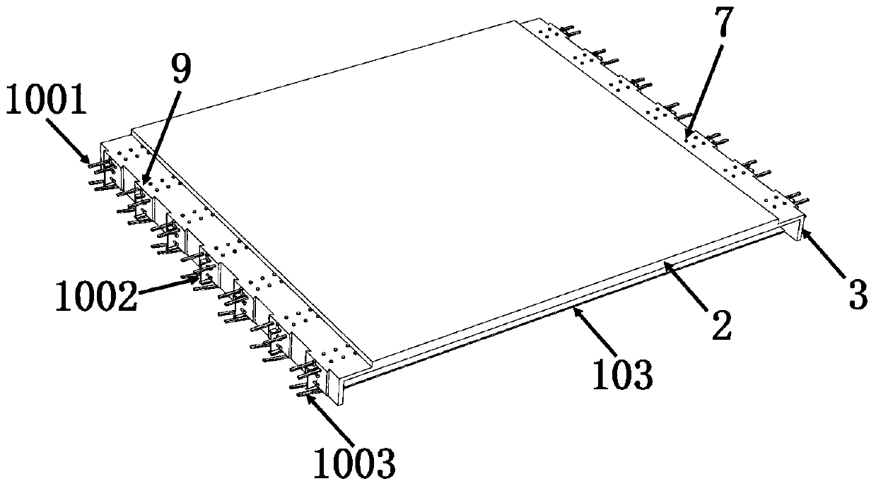
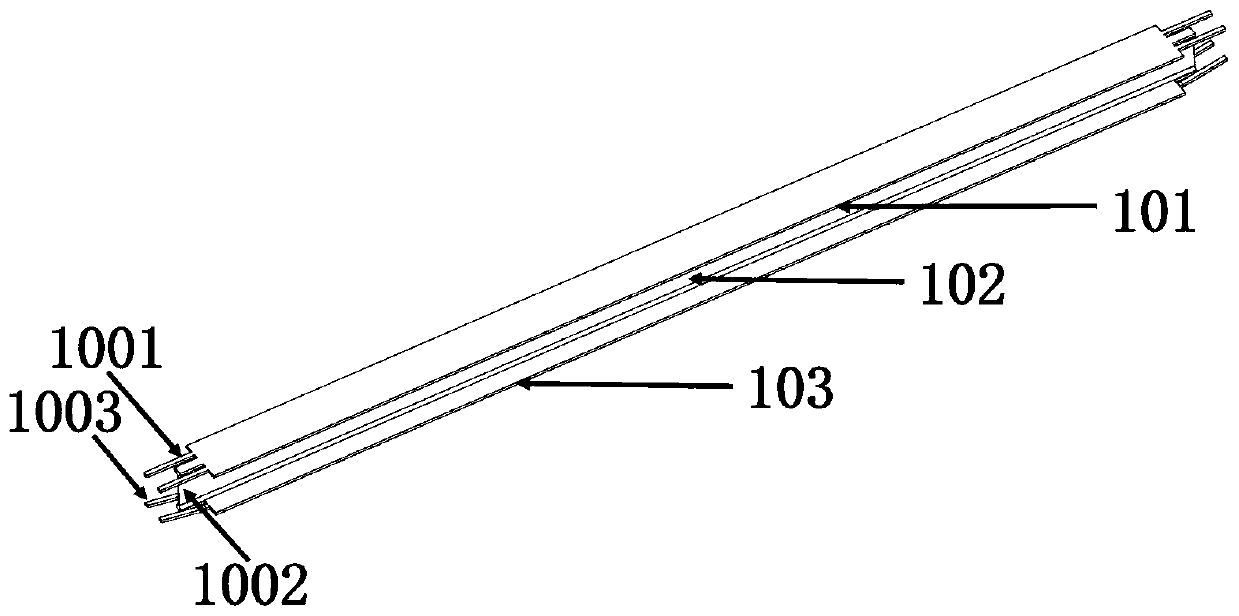
[0071] Such as figure 1 As shown, the steel-UHPC composite plate of this embodiment includes a plurality of steel beams 1 and UHPC boards 2 fixed on the steel beams 1, the steel beams 1 are arranged in parallel along the longitudinal bridge direction, and the steel beams 1 include upper flanges 101, the web 102 and the lower flange 103 (type steel 1 such as I-beam, channel steel, U-shaped steel, etc.), the UHPC plate 2 is fixed on the upper flange 101, the upper flange 101, the web 102 and the lower flange The end of the edge 103 is provided with an upper flange overhang 1001 , a web overhang 1002 and a lower flange overhang 1003 extending outward.

[0072] In this embodiment, the upper flange overhanging section 1001 is a plurality of long straight strips arranged at intervals, and the lower flange overhanging section 1003 is a plurality of intervals arranged and inclined upward (the inclination angle is between 10° and 60°). Can) long straight strips (the lower flange overh...

Embodiment 2

[0094] Such as Figure 20 As shown, the profile steel-UHPC composite plate of this embodiment is different from that of Example 1 in that there is no lower flange 103 in the profile steel 1 (the type of profile steel 1 can be angle steel, T-shaped steel, bulb flat steel, etc.).

[0095] In this embodiment, the schematic diagram of the steel structure is as follows Figure 21 shown.

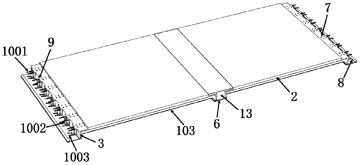
[0096] Such as Figure 22 As shown, the bridge deck in this embodiment is mainly composed of a plurality of above-mentioned steel-UHPC composite plates connected longitudinally and bridgewise, and adjacent bridge decks are connected by cast-in-place connecting parts 13 .

[0097] In this embodiment, the arrangement of the shaped steel 1 in the two adjacent shaped steel-UHPC composite panels can be any of the following structures, such as Figure 23 As shown, the section steels 1 in the adjacent section steel-UHPC composite panels are arranged in one-to-one correspondence. Such as Figure 24 A...


PUM


Abstract

The invention discloses a section steel-UHPC composite board. The section steel-UHPC composite board comprises a plurality of pieces of section steel and UHPC boards fixedly connected to the section steel. Each piece of section steel comprises an upper flange and a web, and the end of the upper flange is provided with an outwardly extending upper flange extension section. The invention also discloses a bridge deck. The bridge deck is mainly formed by connecting a plurality of section steel-UHPC composite boards in the longitudinal bridge direction, the adjacent section steel-UHPC composite boards are connected through a cast-in-situ connection part, and the ends of the upper flanges are provided with upper flange outward extension sections and lower flange outward extension sections that extend towards the insides of the cast-in-situ connection parts respectively. The section steel-UHPC composite board and the bridge deck solve the problems of easiness in cracking of bridge decks in anegative moment region at the transverse joint of the inner fulcrum of a continuous beam bridge and easiness in cracking of a transverse joint between bridge decks at the midspan main beam in the midspan of a cable-stayed bridge.

Description

technical field [0001] The invention belongs to the field of bridge engineering, and in particular relates to a composite plate and a bridge deck for forming bridge decks. Background technique [0002] For steel-concrete continuous system girder bridges, it has been widely used because of its good mechanical performance, less expansion joints, comfortable driving, good economy, and convenient construction. The internal fulcrum will generate a huge negative bending moment, and the long-span continuous girder bridge is very sensitive to its own weight. The increase of the structural self-weight will further increase the negative bending moment of the continuous girder bridge internal fulcrum, which will lead to The tensile stress of the bridge deck is much greater than that of other parts, so there is a risk of cracking of the bridge deck in the inner fulcrum area, which is the main reason for limiting the span of steel-concrete continuous system girder bridges to exceed 150 m...

Claims


Application Information

Patent Timeline
Patent Type & Authority Applications(China)
IPC IPC(8): E01D19/12E01D21/00
CPCE01D19/125E01D21/00
Inventor 邵旭东赵旭东李玉琪曹君辉刘琼
Owner HUNAN UNIV
Learn More