
Annular reciprocating closed electrospinning device

A reciprocating, electrospinning technology, applied in textile and papermaking, filament/thread forming, fiber processing, etc., can solve the problems of waste of spinning solution, reduced spinning efficiency and quality, discontinuous electric field, etc. Yield, overcoming poor uniformity

Pending Publication Date: 2019-07-05
上海帕森纳米科技有限公司
View PDF4 Cites 4 Cited by
  • Summary
  • Abstract
  • Description
  • Claims
  • Application Information

AI Technical Summary

Problems solved by technology

[0003] Yield and stability problems are the two bottlenecks that have always restricted the development of electrospinning technology. Although the output and stability of the electrospinning device have been greatly improved through the efforts of the majority of scientific researchers, it still cannot meet the needs of large-scale production. demand for chemical production
However, the existing problem is that the "edge effect" of electric field mutual interference will be generated between the needles, resulting in a significant deviation of the single-needle jet, the spinning efficiency and quality are reduced, and there are complex spinning devices, easy blockage of the needles, and liquid supply to each needle. Uneven volume, complex liquid supply system, and inconvenient cleaning. After problems with the spinning device, it takes a long time to solve them, which limits large-scale production.
[0005] Needle-free spinning solves the inherent shortcomings of needle spinning. Taylor cones are formed on the surface of the spinning head as much as possible per unit time, thereby increasing the output of nanofibers. One is a spinning electrode represented by a cable, such as The patent with the notification number CN101755079B applies the solution on the cable through a set of reciprocating brushing mechanism. This method provides fresh spinning solution for the electrode through the closed liquid supply system, which is conducive to the stable production. The disadvantages The reason is that the high-voltage static electricity applied to the cable is unevenly distributed in the length direction, and the high-voltage electric field at both ends is higher than that in the middle, which will cause uneven spinning jets during the spinning process, thereby making the collected nanofiber layer uneven. In addition, Since the reciprocating brushing mechanism will remove the unfinished material liquid as waste liquid during the brushing process, it will cause a lot of waste of spinning solution
The other is a spinning electrode that rotates around the axis. For example, the patent with the notification number CN202107802U and the patent with the publication number CN102216502A use spiral blades and springs as the spinning electrodes respectively, although the uneven distribution of the electric field and the reusable solution are solved. However, the existing problem is that these devices all use an open system, and the surface of the polymer spinning solution is exposed to the air, causing a large amount of solvent to volatilize
But the disadvantage is that the position of the parallel ring is fixed, and the electric field between the collector and the collector is discontinuous, which may easily cause poor uniformity of the nanofiber layer received on the collector.

Method used


Image

  • Annular reciprocating closed electrospinning device
  • Annular reciprocating closed electrospinning device
  • Annular reciprocating closed electrospinning device

Examples


Embodiment

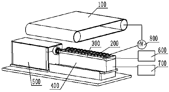
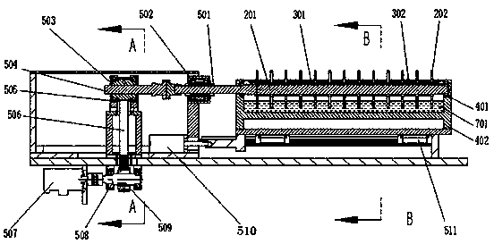
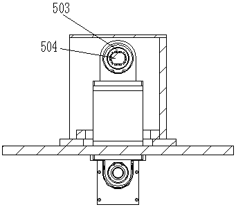
[0108] Such as figure 1 and figure 2 As shown, the mobile rotating mechanism 500 is composed of a linear bearing 501, a rolling bearing 502, a driven synchronous pulley 503, a driven shaft 504, a rolling bearing 505, a synchronous belt 506, a servo motor 507, a driving shaft 508, a driving synchronous pulley 509, a cylinder 510 and 511 linear slides. The driving synchronous pulley 509 has the same tooth profile as the driven synchronous pulley 503 , and the number of teeth is equal, and they are connected together by a synchronous belt 506 . The central hole of the driven synchronous pulley 503 has double-plane steps, and grooves are provided on the two planes and the arc surface to reduce the friction generated when the central shaft reciprocates, as shown in the side sectional view image 3shown. Driven shaft 504 one end has two platform surfaces, cooperates with driven synchronous belt pulley 503 central holes, can make driven synchronous belt pulley 503 drive driven sh...


PUM

PropertyMeasurementUnit
Diameteraaaaaaaaaa
Thicknessaaaaaaaaaa

Abstract

The invention discloses an annular reciprocating closed electrospinning device. The device comprises a fiber collector, a fiber generator, a solution tank, a reciprocating rotating mechanism and a high voltage generating device, wherein the fiber generator is arranged in the solution tank and is in connected transmission with the reciprocating rotating mechanism to achieve the effect that the fiber generator rotates while reciprocating, the fiber generator and the fiber collector are connected with the positive and negative poles of the high voltage generating device respectively, and a high-voltage electrostatic field used for achieving electrospinning is formed between the fiber collector and the fiber generator. The annular reciprocating closed electrospinning device has the advantagesthat through the reciprocating of the fiber generator, the defect of poor uniformity of nanofibers received by the fiber collector, which is caused by the discontinuity of the electric field, can be overcome, and by adding air flow on a sealing cover plate, the yield of the nanofibers can be greatly increased.

Description

technical field [0001] The invention belongs to the technical field of electrostatic spinning devices, and in particular relates to an annular reciprocating closed type electrostatic spinning device. Background technique [0002] In recent years, through a large number of research and experimental comparisons of various nanofiber production methods, electrospinning has gradually become an important method for stably preparing nanofibers. The method has a simple production process and a wide range of applications. It only needs to apply a high-voltage electrostatic field between the nozzle and the receiving electrode, and different kinds of spinning solutions can prepare various functional nanofibers. The types of spinning solutions range from synthetic polymers to natural polymers. All soluble and fusible polymers can be prepared by electrospinning, and the production is stable and the shape is relatively controllable. [0003] Yield and stability problems are the two bottl...

Claims


Application Information

Patent Timeline
IPC IPC(8): D01D5/00
CPCD01D5/0061D01D5/0076
Inventor 陈森
Owner 上海帕森纳米科技有限公司
Learn More