
Building board machining device for construction site

A technology for building boards and processing devices, applied in stone processing equipment, metal processing, work accessories, etc., can solve the problems of difficult to adjust the cutting position, difficult to ensure the progress, slow cutting speed, etc., to achieve convenient adjustment, ingenious structure and design. reasonable effect

Pending Publication Date: 2019-07-05
SHANDONG UNIV OF TECH
View PDF9 Cites 3 Cited by
  • Summary
  • Abstract
  • Description
  • Claims
  • Application Information

AI Technical Summary

Problems solved by technology

[0004] During the construction on the construction site, various types of boards are often used, such as ceramic tiles, resin boards, etc. When used on the construction site, the boards need to be cut according to the installation requirements. At present, when cutting the boards, many workers Cutting with a hand-held cutting machine, using this method, the accuracy of cutting depends on the experience of the workers, it is difficult to guarantee the progress, and, in order to prevent cutting errors, the cutting speed is often too slow
Patent document 2016110304712 discloses an angle-adjustable tile cutter, which is set on the slide rail, the plate is placed on the lower side of the slide rail, and the cutting machine slides on the slide rail to complete the cutting of the plate, and, It can also adjust the cutting angle by rotating the slide rail. In this way, although the moving track of the cutting machine can be determined by the slide rail, since the plate is placed in the storage tank, it is fixed to the fixed end of the top bar. , making it difficult to adjust the cutting position, unable to meet production needs
Therefore, the existing sheet material processing device has been unable to effectively meet the needs of production

Method used


Image

  • Building board machining device for construction site
  • Building board machining device for construction site
  • Building board machining device for construction site

Examples


Embodiment Construction

[0026] In order to clearly illustrate the technical features of this solution, the present invention will be described in detail below through specific implementation modes and in conjunction with the accompanying drawings.

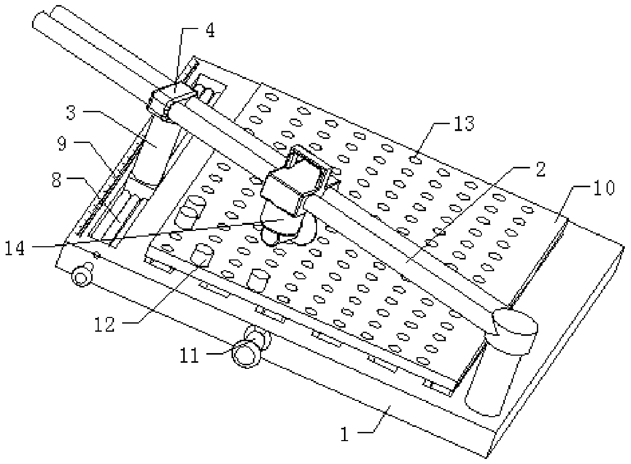
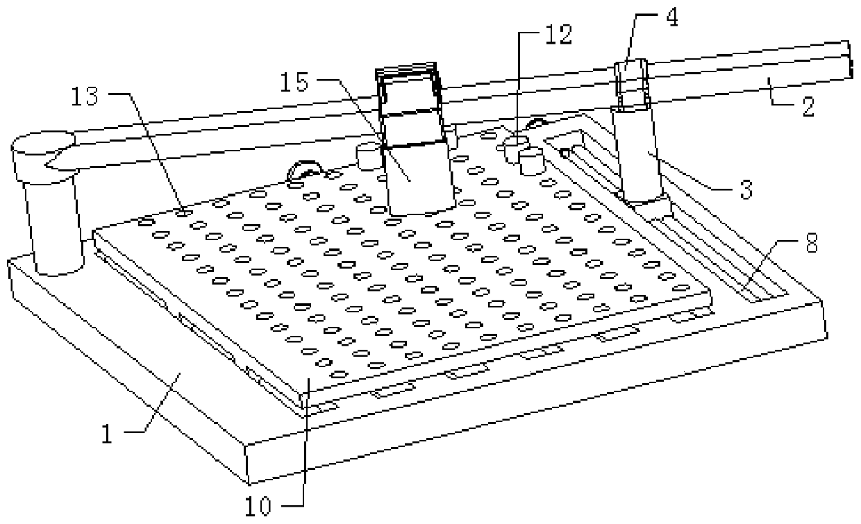
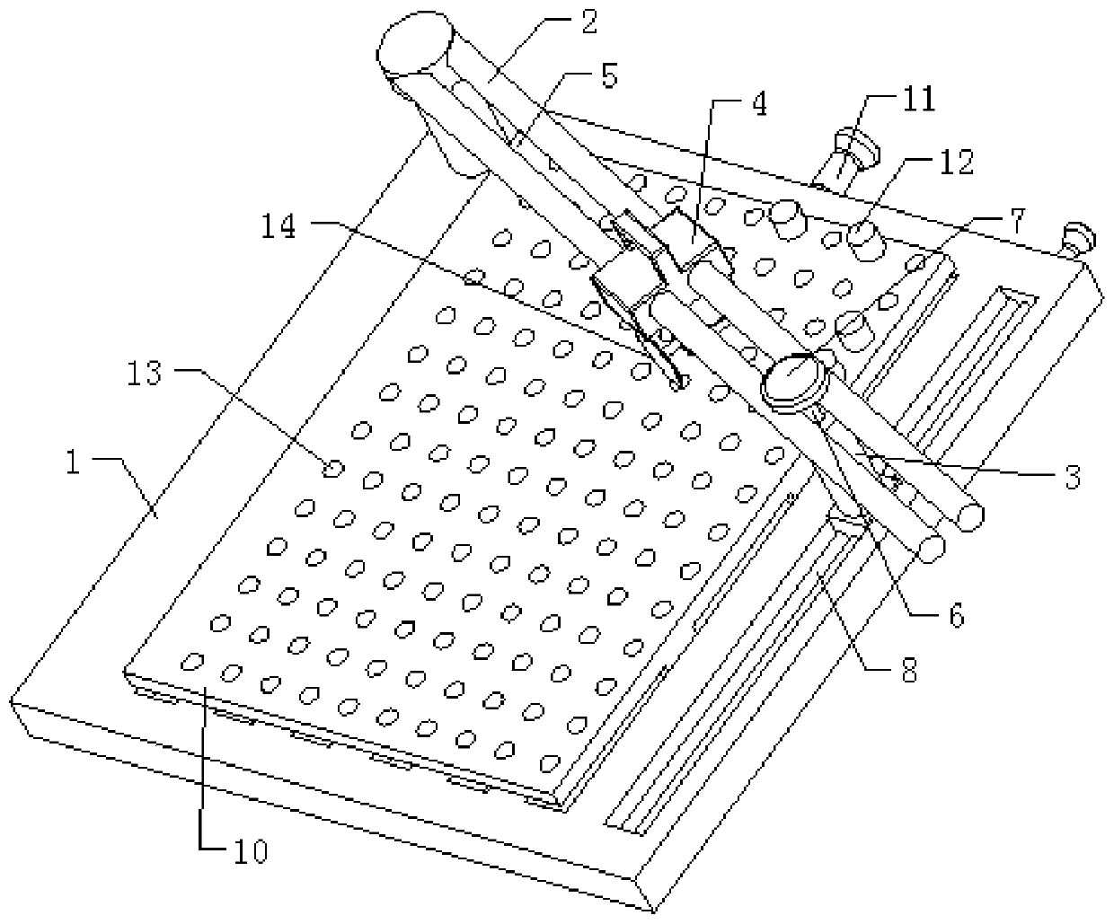
[0027] Embodiments of the present invention are as Figure 1-4 As shown, a building board processing device for a construction site includes: a base frame 1; a slide rail 2 assembly, including a slide rail 2 arranged on the upper side of the base frame 1, and a sliding pillar 3 slidingly connected with the base frame 1 , wherein, one end of the slide rail 2 away from the sliding strut 3 is rotationally connected with the chassis 1, the other end passes through the upper side of the sliding strut 3, and is connected between the sliding strut 3 and the sliding strut 3. A sliding connection structure is provided between the rails 2, and the sliding connection structure is arranged so that when the sliding strut 3 slides, the sliding rail 2 intersects the axi...


PUM


Abstract

The invention relates to the field of building equipment, in particular to building board machining device for a construction site. The device comprises a bottom frame, a sliding rail assembly, a cutting assembly and a positioning assembly. The sliding rail assembly comprises a sliding rail on the upper side of the bottom frame, and a sliding supporting column; the end, away from the sliding supporting column, of the sliding rail is rotatably connected with the bottom frame, the other end penetrates through the upper side of the sliding supporting column, a slippage connection structure is arranged between the sliding supporting column and the sliding rail, through arrangement of the slippage connection structure, when the sliding supporting column slides, the sliding rail is crossed withthe axis of the sliding supporting column, and a locking structure is arranged between the sliding supporting column and the bottom frame. The cutting assembly is arranged on the sliding rail in a sliding manner, the positioning assembly comprises a board supporting part arranged on the bottom frame, and a board positioning part arranged on the top of the board supporting part, the board supporting part is consistent with the sliding direction of the sliding supporting column relative to the sliding direction of the bottom frame, the device is ingenious in design, reasonable in design, and capable of conveniently adjusting the board cutting angle and cutting position, and obviously, the production needs can be effectively met.

Description

[0001] Technical field: [0002] The invention relates to the field of construction equipment, in particular to a construction board processing device for construction sites. [0003] Background technique: [0004] During construction on a construction site, various types of boards are often used, such as ceramic tiles, resin boards, etc. When used on a construction site, it is often necessary to cut the boards according to the installation requirements. At present, when cutting the boards, many workers Cutting with a hand-held cutting machine, using this method, the accuracy of cutting depends on the experience of the workers, it is difficult to guarantee the progress, and in order to prevent cutting errors, the cutting speed is often too slow. Patent document 2016110304712 discloses an angle-adjustable tile cutter, which is set on the slide rail, the plate is placed on the lower side of the slide rail, and the cutting machine slides on the slide rail to complete the cutting o...

Claims


Application Information

Patent Timeline
Patent Type & Authority Applications(China)
IPC IPC(8): B26D1/15B26D7/01B26D7/00B08B15/02B28D1/24B28D7/04B28D7/02B28D7/00
CPCB26D1/15B26D7/01B26D7/0006B26D7/00B08B15/02B28D1/24B28D7/04B28D7/02B28D7/00
Inventor 李素蕾
Owner SHANDONG UNIV OF TECH
Learn More