Corner stamping and blanking rough die for metal cutting part top block frame air defence stress marks

A metal cutting and stress trace technology, applied in metal processing equipment, forming tools, manufacturing tools, etc., can solve the problems of limit deviation, surface texture reflection, upper or lower initial position of fitting, etc.

Inactive Publication Date: 2019-07-05
泉州市泉港区玛纳利华工业科技有限公司
View PDF0 Cites 3 Cited by
  • Summary
  • Abstract
  • Description
  • Claims
  • Application Information

AI Technical Summary

Problems solved by technology

[0004] Aiming at the deficiencies in the prior art, the purpose of the present invention is to provide a corner stamping and roughening mold for preventing stress marks on the top block of the metal cutting part, so as to solve the problem that the pressure resistance of the thimble cylinder of the stamping mold is stronger than that of the conventional mold. Make the holding pressure and cold and heat homogeneous and efficient, but the up and down movement of the top plate and the top block often has a certain limit deviation, and the initial position of the fitting will be higher or lower, which will cause the longitudinal side to be too wide Stress marks will be pulled out, and the vertical narrowing and upper and lower horizontal planes will also pull out stress marks, resulting in the appearance of glossy areas on the surface of the product corresponding to the back bones, ribs, glue-added or glue-reduced boundaries, and then the overall product is made of wool felt. After wiping, it will cause reflections on the surface texture, which is often called "light body, light print, bone shadow" defects.

Method used


Image

  • Corner stamping and blanking rough die for metal cutting part top block frame air defence stress marks
  • Corner stamping and blanking rough die for metal cutting part top block frame air defence stress marks
  • Corner stamping and blanking rough die for metal cutting part top block frame air defence stress marks

Examples


Embodiment Construction

[0032]In order to make the technical means, creative features, goals and effects achieved by the present invention easy to understand, the present invention will be further described below in conjunction with specific embodiments.

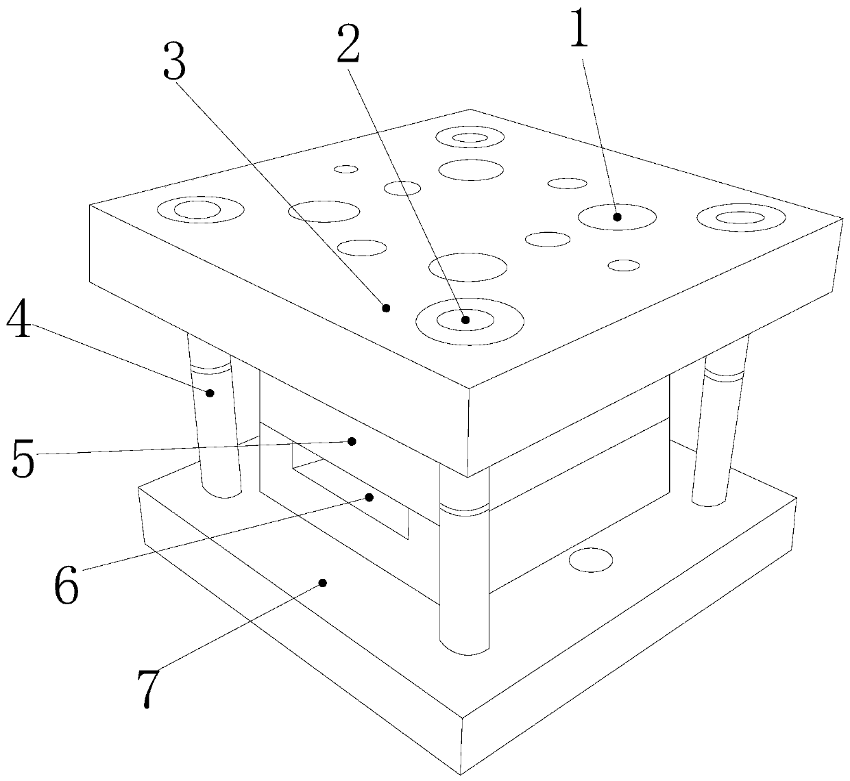
[0033] see Figure 1-Figure 9 , the present invention provides a corner stamping and roughening mold for preventing stress marks on the top block of metal cutting parts. Groove 5, thimble groove 6, base 7, the base 7 is buckled together with the top cover plate 3 through the clamping column 4, and the top cover plate 3 and the base 7 are respectively installed in the parting stamping groove 5 The upper and lower sides of the upper and lower sides are parallel to each other, the parting stamping groove 5 and the thimble groove 6 are nested into one body, and the air pipe insertion hole 1 and the rubber ring 2 are respectively provided with more than two and are both nested in the top cover plate 3 inside and on the same horizontal plane, the clampi...


PUM


Abstract

The invention discloses a corner stamping and blanking rough die for a metal cutting part top block frame air defence stress marks, and the structure comprises an air pipe inserting hole, a rubber ring, a top cover plate block, a mold locking column, a parting stamping groove, a centre groove and a base. According to the invention, the matching of the parting stamping groove and the centre grooveis realize, a traditional single-part ejector sleeve is converted into a four-position ejector pin barrel body and a top block separating frame mechanism, the center end of a mold plate surface at thefour sides can be conveniently positioned, the corner deviation during stamping of a top plate can be prevented, stable inclined surface centralizing treatment phenomenon, stopping work of mold equipment after the ejector sleeve damage is also prevented, then a needle bottom sliding seat plate is used for pulling and positioning from a four-position cross to a three-position Y-shaped supporting track, replacement of the ejector sleeve loss is realized and the work is continuous, the effect that the ejector sleeve can be displaced and the top block can be clamped can be formed under the stamping internal environment, the probability of the stress mark in the product can be reduced, so that the top pressure position of the plate is continuously and effectively reset, when the ejector pin groove is conveniently discharged, the single performance of the ejector sleeve structure is optimized, and the multi-direction pressure-resisting pushing effect is improved.

Description

technical field [0001] The invention relates to a stamping and roughening mold for edge corner stamping and anti-stress marks of the top block of a metal cutting part, which belongs to the field of molds. Background technique [0002] Metal cutting is the next cutting operation after injection molded parts are formed. It is very important for corner trimming and polishing of metal parts. It is the function of stamping dies and the last step of processing of molded products. It is often Cooperate with the stamping spindle to form the recoil pressure, and protect the mold shell from cracks caused by excessive pressure. The shortcomings of the current technology to be optimized are: [0003] The pressure resistance of the thimble cylinder of the stamping die is stronger than that of the conventional die, which makes the holding pressure and heat and cold homogeneous and efficient, but the upper and lower movements of the top plate and the top block often have a certain limit de...

Claims


Application Information

Patent Timeline
Patent Type & Authority Applications(China)
IPC IPC(8): B21D37/10B21D37/12
CPCB21D37/10B21D37/12
Inventor 谢成宗谢萍萍张莹
Owner 泉州市泉港区玛纳利华工业科技有限公司
Why Eureka
Try Eureka