
Hydraulically operated transmission

A transmission and working technology, applied in the direction of components with teeth, transmission control, belt/chain/gear, etc., can solve problems such as complex structure and complex control

Active Publication Date: 2019-07-02
MAZDA MOTOR CORP
View PDF5 Cites 0 Cited by
  • Summary
  • Abstract
  • Description
  • Claims
  • Application Information

AI Technical Summary

Problems solved by technology

[0006] However, the structure of the above-mentioned Patent Document 1 has the following problems: in order to adjust the supply amount of lubricating oil supplied to the starting clutch, it is necessary to control both the pressure reducing valve and the oil injection amount of the oil pump, resulting in complicated structure and complicated control

Method used


Image

  • Hydraulically operated transmission
  • Hydraulically operated transmission
  • Hydraulically operated transmission

Examples


Embodiment Construction

[0023] Hereinafter, exemplary embodiments will be described in detail with reference to the drawings.

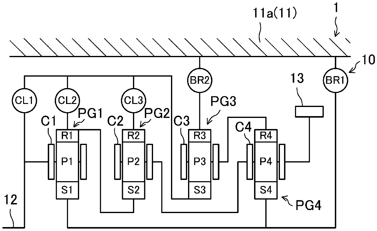
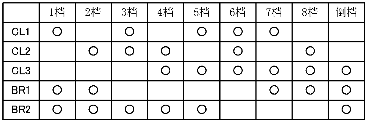
[0024] figure 1 A hydraulic transmission 1 (hereinafter referred to as a transmission 1 ) according to an exemplary embodiment is shown. The transmission 1 is an automatic transmission mounted on a vehicle, which implements eight forward gears and one reverse gear. The transmission 1 has a transmission case 11 and a speed change mechanism 10. The transmission case 11 has a cylindrical shape. The speed change mechanism 10 is provided in the transmission case 11. motivation.

[0025] The transmission mechanism 10 has an input shaft 12 corresponding to an input portion of the transmission 1 and an output gear 13 corresponding to an output portion of the transmission 1 . The input shaft 12 is directly connected to the output shaft of the driving source. That is, in the present embodiment, no torque converter is provided between the output shaft of the drive source and the i...


PUM


Abstract

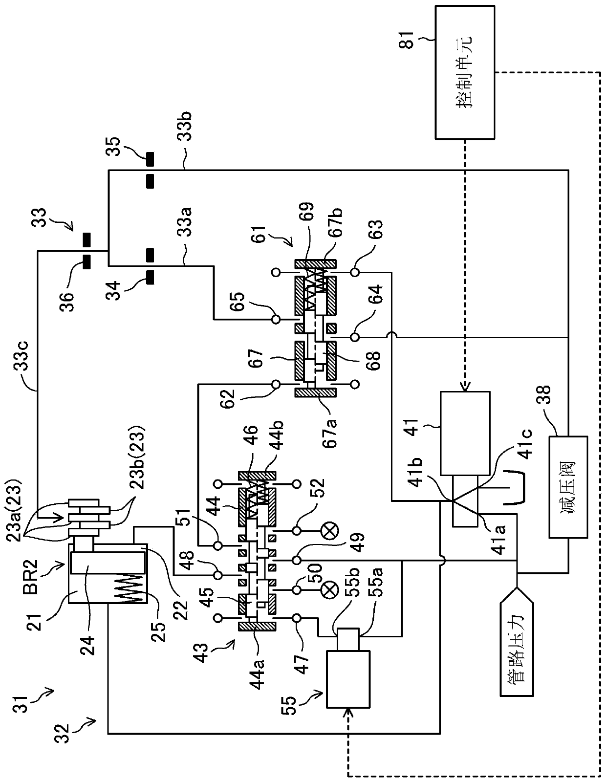
A hydraulically operated transmission (1) comprises: a pressure regulating device (pressure regulating solenoid valve 41) that regulates the pressure of a hydraulic fluid to a hydraulic pressure engagement chamber (21) of a friction engagement element (second brake (BR2)) for starting a vehicle; and a lubrication control valve (61) that is disposed in a lubricating oil supply circuit (33) to supply lubricating oil to the friction engagement element. When the friction engagement element is engaged while starting the vehicle, the lubrication control valve (61) operates so that the flow rate of the lubricating oil supplied to the friction engagement element when the regulating pressure due to the pressure regulating device is set to be a first prescribed pressure, which is a complete engagement state, or higher and is lower than a second prescribed pressure set to a value less than the high pressure is greater than when the regulating pressure is equal to the second prescribed pressure orgreater.

Description

technical field [0001] The invention relates to a hydraulic working transmission installed on a vehicle. Background technique [0002] Hitherto, a hydraulically operated transmission including a launch clutch is known. When the vehicle is started, the hydraulic oil is supplied to the engagement hydraulic chamber, and the start clutch enters the fully engaged state from the disengaged state via the slipping state (for example, refer to Patent Document 1). In order to cool and lubricate the starting clutch, lubricating oil is supplied to the starting clutch. Here, under the structure that does not adjust the supply amount of lubricating oil supplied to the start clutch, from the viewpoint of ensuring reliability, the supply amount supplied to the start clutch is always equivalent to the most severe condition of the start clutch (such as starting The amount of lubricating oil supplied when the clutch is slipping. If a large amount of lubricating oil is not needed in this cas...

Claims


Application Information

Patent Timeline
Patent Type & Authority Applications(China)
IPC IPC(8): F16H61/00
CPCF16H2061/0037F16H61/0021F16H57/0435F16H61/0206F16H57/0473
Inventor 石山贵士佐藤文俊冈山裕之川上益弘木下友和
Owner MAZDA MOTOR CORP
Learn More