System and method for recovering calcium carbonate and sulfur by calcining gypsum

A calcium carbonate and calcination technology, applied in the preparation/purification of calcium carbonate/strontium/barium, sulfur, etc., can solve the problems of limiting the application scope of sulfur resources, difficulty in storing and transporting sulfuric acid, affecting the stability of the sulfur market, etc. Chemical utilization, improve the utilization rate of raw materials, and prevent the effect of over-burning

Active Publication Date: 2019-06-25
SHANDONG UNIV
View PDF5 Cites 6 Cited by
  • Summary
  • Abstract
  • Description
  • Claims
  • Application Information

AI Technical Summary

Problems solved by technology

Although the utilization rate of phosphogypsum and desulfurized gypsum in Japan is over 90% (there is a serious lack of natural gypsum resources in Japan), the amount is relatively small, and it is also in low-end low-tech fields such as building materials
[0006] On the other hand, the inventors found that our country is short of sulfur resources, and a large amount of sulfur needs to be imported from abroad every year. Sulfur is one of the indispensable chemical raw materials. A large amount of reliance on imports will not only affect the stability of the domestic sulfur market, but also be of great importance to national security. potential threat
At present, most of the flue gas sulfur resource utilization technologies in my country are used to prepare sulfuric acid. However, due to the difficulty in storage and transportation of sulfuric acid, it can only be supplied point-to-point, which greatly limits the application range of sulfur resources.

Method used


Image

  • System and method for recovering calcium carbonate and sulfur by calcining gypsum

Examples


Embodiment 1

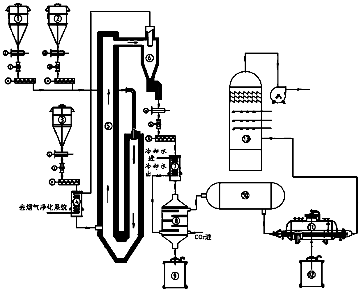
[0054] A system for recovering calcium carbonate and sulfur by calcination of gypsum, including: coal gasification-calcination U-shaped furnace 5, H 2 O-CO 2 Processor 8, Claus reactor 10, the coal gasification section on the right side of the coal gasification-calcination U-shaped furnace 5 is connected to the calcium-based material storage bin 1 and the coal powder storage bin 2 respectively, and the coal gasification-calcination U-shaped The calcining section on the left side of the U-shaped furnace 5 is connected to the gypsum storage bin 3, the top of the calcining section on the left side of the coal gasification-calcination U-shaped furnace 5 is connected to the high-temperature separator 6, and the bottom of the high-temperature separator 6 is cooled with calcium sulfide-calcium oxide Device 7, H 2 O-CO 2 Processor 8, calcium carbonate storage bin 9 are connected successively, and described H 2 O-CO 2The processor 8 is also connected to a Claus reactor 10 , and the...

Embodiment 2

[0059] A system for recovering calcium carbonate and sulfur by calcination of gypsum, including: coal gasification-calcination U-shaped furnace 5, H 2 O-CO 2 Processor 8, Claus reactor 10, the coal gasification section on the right side of the coal gasification-calcination U-shaped furnace 5 is connected to the calcium-based material storage bin 1 and the coal powder storage bin 2 respectively, and the coal gasification-calcination U-shaped The calcining section on the left side of the U-shaped furnace 5 is connected to the gypsum storage bin 3, the top of the calcining section on the left side of the coal gasification-calcination U-shaped furnace 5 is connected to the high-temperature separator 6, and the bottom of the high-temperature separator 6 is cooled with calcium sulfide-calcium oxide Device 7, H 2 O-CO 2 Processor 8, calcium carbonate storage bin 9 are connected successively, and described H 2 O-CO 2 The processor 8 is also connected to a Claus reactor 10 , and th...

Embodiment 3

[0064] A system for recovering calcium carbonate and sulfur by calcination of gypsum, including: coal gasification-calcination U-shaped furnace 5, H 2 O-CO 2 Processor 8, Claus reactor 10, the coal gasification section on the right side of the coal gasification-calcination U-shaped furnace 5 is connected to the calcium-based material storage bin 1 and the coal powder storage bin 2 respectively, and the coal gasification-calcination U-shaped The calcining section on the left side of the U-shaped furnace 5 is connected to the gypsum storage bin 3, the top of the calcining section on the left side of the coal gasification-calcination U-shaped furnace 5 is connected to the high-temperature separator 6, and the bottom of the high-temperature separator 6 is cooled with calcium sulfide-calcium oxide Device 7, H 2 O-CO 2 Processor 8, calcium carbonate storage bin 9 are connected successively, and described H 2 O-CO 2 The processor 8 is also connected to a Claus reactor 10 , and th...


PUM

PropertyMeasurementUnit
particle diameteraaaaaaaaaa

Abstract

The invention relates to a system and a method for recovering calcium carbonate and sulfur by calcining gypsum. The system comprises a coal gasification-calcination U-shaped furnace, a H2O-CO2 processor and a Klaus reactor. A coal gasification section on the right side of the coal gasification-calcination U-shaped furnace is respectively connected with a calcium-based material storage bin and a coal powder storage bin. A calcination section on the left side of the coal gasification-calcination U-shaped furnace is connected with a gypsum storage bin. The top end of the calcination section on the left side of the coal gasification-calcination U-shaped furnace is connected with a high-temperature separator. The bottom of the high-temperature separator is sequentially connected with a calciumsulfide-calcium oxide cooler, a H2O-CO2 processor and a calcium carbonate storage bin. The H2O-CO2 processor is also connected with the Klaus reactor. The Klaus reactor is sequentially connected witha sulfur recovery device and a sulfur storage bin. The sulfur recovery device is also connected with a flue gas purification system. The system and the method are used for preparing the sulfur and a byproduct, calcium carbonate powder, by using the industrial byproduct gypsum which is difficult to treat, and the byproduct calcium carbonate powder can replace limestone to be used as a desulfurization and denitrification agent for recycling and can also be used as a catalyst of a coal gasification process.

Description

technical field [0001] The invention belongs to the field of resource utilization of solid waste, and in particular relates to a technique and method for recovering calcium carbonate and sulfur by calcining gypsum. Background technique [0002] The information disclosed in this background section is only intended to increase the understanding of the general background of the present invention, and is not necessarily taken as an acknowledgment or any form of suggestion that the information constitutes the prior art already known to those skilled in the art. [0003] At present, the production of industrial by-product gypsum in my country is about 118 million tons, and the comprehensive utilization rate is only 38%. Among them, desulfurization gypsum is about 43 million tons, with a comprehensive utilization rate of about 56%; phosphogypsum is about 50 million tons, with a comprehensive utilization rate of about 20%; other by-product gypsum is about 25 million tons, with a com...

Claims


Application Information

Patent Timeline
Patent Type & Authority Applications(China)
IPC IPC(8): C01F11/18C01B17/02
Inventor 马春元夏霄张立强崔琳王涛赵希强李军冯太
Owner SHANDONG UNIV
Why Eureka
Try Eureka