Multi-section reinforcement cage floor wall inclinometer pipe connection device and installation method

A technology for connection devices and installation methods, which is applied in the direction of measuring devices, sheet pile walls, buildings, etc., can solve the problems of high difficulty in operation, difficulty in work, and heavy workload, so as to avoid difficult operation, improve construction efficiency, and docking The effect of easy operation

Pending Publication Date: 2019-06-18
SHANGHAI GEOTECHN INVESTIGATIONS & DESIGN INST
View PDF0 Cites 1 Cited by
  • Summary
  • Abstract
  • Description
  • Claims
  • Application Information

AI Technical Summary

Problems solved by technology

[0003] The following defects exist in the above steps: when the reinforcement cage is docked, it is required that the lateral distance between the joints of the inclinometer pipes in the upper and lower sections of the reinforcement cage should not be too large. For the cylindrical beam joint at the top of the pipe, the requirements are strict; when the cylindrical beam joint is used for inclinometer pipe docking, it is necessary to move the unfixed inclinometer tube of the upper section and insert it into the cylindrical beam joint, which is difficult to work; if the upper joint The length of the steel cage is longer, the required inclinometer tube increases, the weight of the inclinometer tube increases, and the difficulty of manually moving the inclinometer tube increases during docking; after the docking is completed, the construction unit needs to slow down the speed of lowering the upper section of the steel cage Cooperate to complete the fixation of the inclinometer tube in the upper section
In summary, for the installation of multi-section steel cage inclinometer pipes, the traditional method is complex in procedure, difficult in operation, heavy in workload and affects construction efficiency

Method used


Image

  • Multi-section reinforcement cage floor wall inclinometer pipe connection device and installation method
  • Multi-section reinforcement cage floor wall inclinometer pipe connection device and installation method
  • Multi-section reinforcement cage floor wall inclinometer pipe connection device and installation method

Examples


Embodiment Construction

[0029] The preferred embodiments of the present invention will be described in detail below in conjunction with the accompanying drawings, so that the advantages and features of the present invention can be more easily understood by those skilled in the art, so as to define the protection scope of the present invention more clearly.

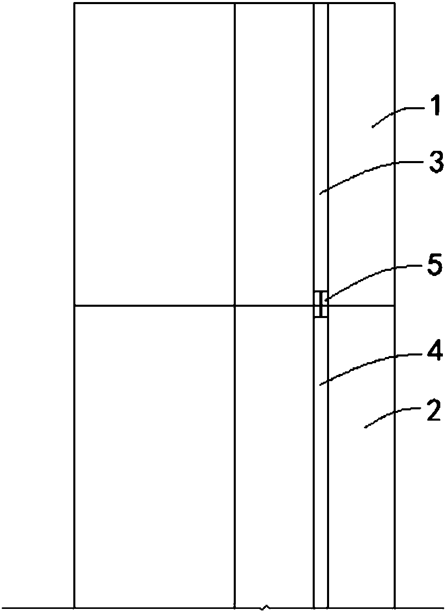
[0030] refer to Figure 1-5 As shown, in the multi-section reinforcement cage ground wall inclinometer pipe connecting device of the present invention, the reinforcement cage includes multi-section reinforcement cages connected up and down in sequence, and the inner sides of the upper section reinforcement cage 1 and the lower section reinforcement cage 2 are respectively vertically provided with upper and lower reinforcement cages. The inclinometer tube 3 and the inclinometer tube 4 in the upper section correspond to the inclinometer tube 4 in the upper section, and the inclinometer tube 3 in the upper section and the inclinometer tube in the low...


PUM


Abstract

The invention discloses a multi-section reinforcement cage floor wall inclinometer pipe connection device and an installation method. Reinforcement cages include multiple sections of reinforcement cages, which are sequentially connected vertically; the inner sides of the upper reinforcement cage and the lower reinforcement cage are respectively provided with an upper inclinometer pipe and a lowerinclinometer pipe vertically; the upper inclinometer pipe corresponds to the lower inclinometer pipe; the upper inclinometer pipe and the lower inclinometer pipe are formed by connecting multiple sections of inclinometer pipe bodies; the structures of the inclinometer pipe bodies are same; the connection device comprises a connection ring; and the bottom of the upper inclinometer pipe is connectedwith the top of the lower inclinometer pipe through the connection ring, wherein the connection ring is formed by a first semicircular beam section and a second semicircular beam section in a mutualencircling manner. According to the multi-section reinforcement cage floor wall inclinometer pipe connection device and the installation method in the invention, the inclinometer pipes do not need tobe bound and fixed when the upper and lower reinforcement cages are put downwardly; the floor wall construction efficiency is increased; and the problems of high operation difficulty, high workload and the like due to the fact that the upper inclinometer pipe is not fixed in the existing method can be avoided.

Description

technical field [0001] The invention relates to the technical field of engineering monitoring equipment, in particular to a connection device and an installation method for a multi-section steel cage ground wall inclinometer pipe connection device. Background technique [0002] At this stage, when the geotechnical engineering enclosure structure is a multi-section ground wall reinforcement cage, the installation method of the inclinometer tube for the deformation monitoring component of the ground wall enclosure structure is: select a vertical steel bar in the first section of the reinforcement cage to bind and fix it Inclinometer tube; the inclinometer tube of the upper steel cage is not completely fixed; when the steel cage is docked, the operator first fixes the cylindrical beam joint on the top of the lower section of the inclinometer tube, and adjusts the position of the upper section of the inclinometer tube to place the upper section The inclinometer tube is inserted ...

Claims


Application Information

Patent Timeline
Patent Type & Authority Applications(China)
IPC IPC(8): G01B21/32E02D5/18
Inventor 戴加东褚伟洪陈卫南刘丹周本辰成龙赵自强
Owner SHANGHAI GEOTECHN INVESTIGATIONS & DESIGN INST
Why Eureka
Try Eureka