
Travel motor delay brake valve and travel motor

A technology for traveling motors and brake valves, which is applied in the fields of hydraulic pressure and machinery, and can solve problems such as delay time mismatch, heat generation, friction plate sintering, etc., and achieve the effects of solving friction plate sintering, improving reliability, and low cost

Active Publication Date: 2020-05-08
JIANGSU ADVANCED CONSTR MASCH INNOVATION CENT LTD +1
View PDF6 Cites 0 Cited by
  • Summary
  • Abstract
  • Description
  • Claims
  • Application Information

AI Technical Summary

Problems solved by technology

[0006] The invention proposes a two-position two-way delay brake valve with a built-in hydraulic travel motor end cover, which effectively solves the common problem in the market that the delay brake valve is externally installed, and simplifies the structure and operation of the delay brake valve. The internal flow channel ensures that the parking brake can be released quickly when the motor starts. When the motor stops, the parking brake lags behind the hydraulic brake. The brake delay time is adjustable, which solves the friction caused by the mismatch of delay time Chip sintering, heating and other problems

Method used


Image

  • Travel motor delay brake valve and travel motor
  • Travel motor delay brake valve and travel motor
  • Travel motor delay brake valve and travel motor

Examples


Embodiment 1

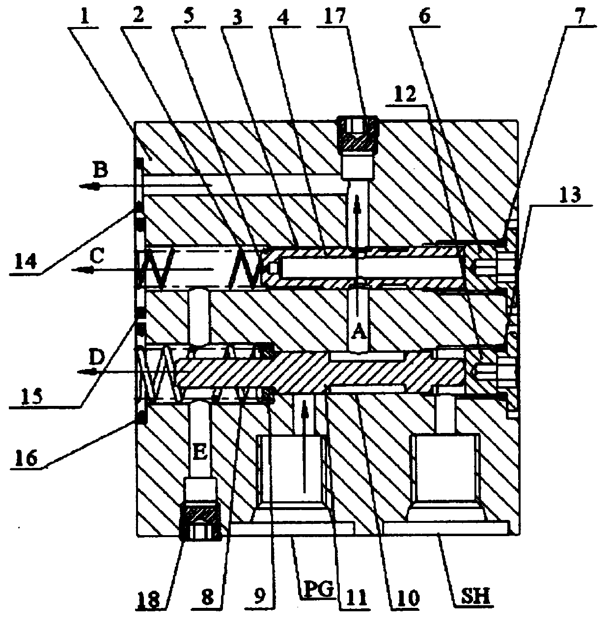
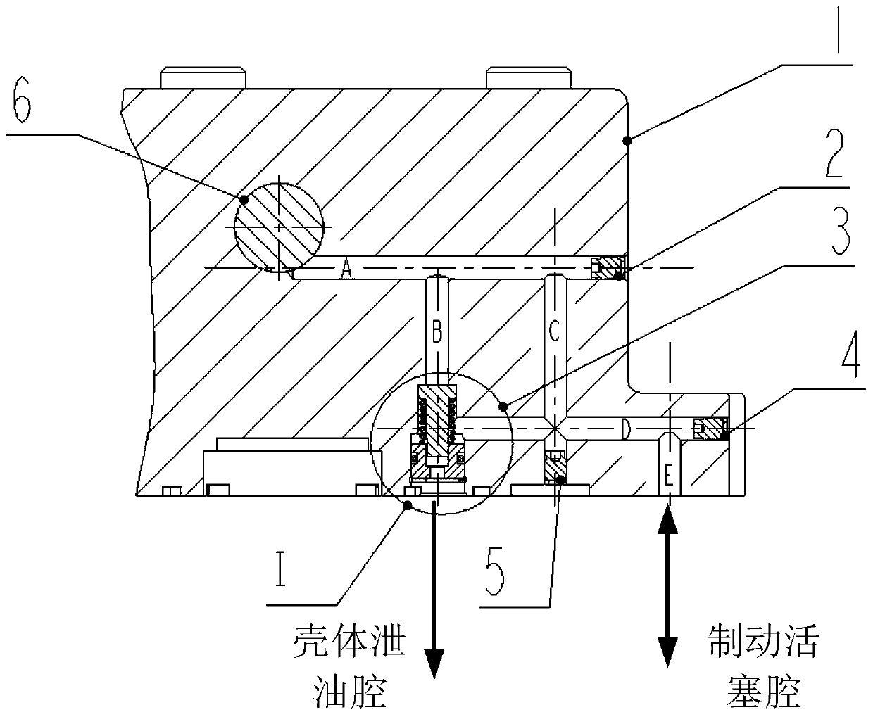
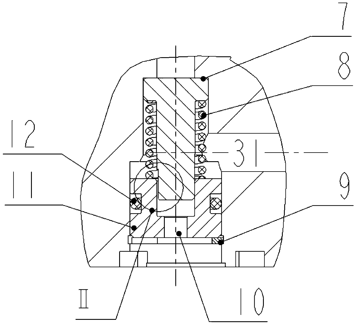
[0041] The new hydraulic travel motor delay brake valve of the present invention adopts Figure 2 to Figure 4 In the shown structure, the delay brake valve 3 is built in the travel motor end cover 1, and the delay brake valve 3 is composed of a valve core 7, a return spring 8, a retaining ring 9, a valve seat 11 and an O-ring 12. One end of the valve core 7 is inserted into the valve seat 11 and can move relative to the valve seat. The return spring 8 is sleeved on the valve core 7 and clamped by the valve core 7 and the valve seat 11 . A damping groove 71 is opened on the valve core 7; an oil drain hole 10 that can lead to the motor housing drain cavity is opened in the groove of the valve seat facing the valve core; when the valve core is in the first relative position relative to the valve seat, the damping The groove is connected with the bypass oil passage, and the oil in the bypass oil passage flows to the oil drain hole through the damping groove; when the valve core is...

Embodiment 2

[0045] On the basis of Example 1, combined with Figure 2 to Figure 4 , in this embodiment, for the convenience of processing, the bypass oil passage can be specifically set as several oil passages, including oil passages A, B, C, D, E, and an auxetic plug 2 is used for the external unused ports , 4, 5 are blocked.

[0046]One end of the oil passage A is connected to the high-pressure chamber of the balance valve 6, and the other end is sealed by the auxetic plug 2. One end of the oil passage B is connected with the oil passage A, and the other end is connected with the delay brake valve 3 . Oil passage C communicates with oil passage A and delay brake valve spring chamber 31 respectively, and the bottom of oil passage C is sealed by an auxetic plug 5 . Oil passage D is respectively connected with oil passage C, oil passage E and delay brake valve spring chamber 31, the right end of oil passage D is sealed by auxetic plug 4, one end of oil passage E is connected with oil pas...


PUM


Abstract

The invention discloses a delay brake valve of a walking motor and the walking motor. The delay brake valve comprises a valve seat, a valve core and a reset spring, wherein the reset spring is arranged on the valve core in a sleeving manner and clamped by the valve core and the valve seat; a damping groove is formed in the valve core; an oil leaking hole capable of communicating with an oil leaking cavity of a motor housing is formed in a groove, facing the valve core, of the valve seat; when the valve core is located at a first relative position relative to the valve seat, the damping groovecommunicates with a bypass oil pipeline, and oil in the bypass oil pipeline flows towards the oil leaking hole via the damping groove; and when the valve core is located at a second relative positionrelative to the valve seat, the damping groove is blocked by the valve seat, and the oil in the bypass oil pipeline directly flows to a brake piston mechanism. The delay brake valve ensures that whenthe motor is in a starting mode, parking brake can be rapidly canceled, and when the motor is in a parking mode, parking brake is lagged behind hydraulic brake, and brake delay time is adjustable. Theproblems of brake pad sintering, heating and the like caused by unmatched delay time are solved. The reliability of the walking motor is improved when processing cost is reduced and repair difficultyis lowered.

Description

technical field [0001] The invention relates to the fields of hydraulic pressure and machinery, in particular to a traveling motor delay brake valve and a traveling motor. Background technique [0002] Various types of crawler machinery are widely used in civil, transportation, water conservancy projects, mining and mechanized construction of modern military projects. Its travel drive device is mostly composed of a swash plate type plunger motor with a star reducer, which is called a travel motor. [0003] The travel motor generally requires two braking modes: hydraulic brake and parking brake, which are reflected on the plunger motor of the drive unit, that is, the plunger motor is required to have two brake modes. When the excavator is about to start, it is often required that the travel motor can quickly release the parking brake, so as to avoid the situation that the hydraulic energy drives the plunger motor to run, and the parking brake is still not released, which wil...

Claims


Application Information

Patent Timeline
Patent Type & Authority Patents(China)
IPC IPC(8): F15B13/01F15B21/00
Inventor 肖刚李正祥汤和荣
Owner JIANGSU ADVANCED CONSTR MASCH INNOVATION CENT LTD
Learn More