
Internal combustion engine and valve drive unit thereof

A technology for internal combustion engines and driving devices, applied to engine components, machines/engines, valve devices, etc., can solve problems such as large construction space, high structure, and heavy weight, and achieve low structural cost, reduced weight, and simple and reliable structure Effect

Active Publication Date: 2013-04-10
DR ING H C F PORSCHE AG
View PDF9 Cites 14 Cited by
  • Summary
  • Abstract
  • Description
  • Claims
  • Application Information

AI Technical Summary

Problems solved by technology

On the one hand this results in a relatively high construction effort, on the other hand such solutions require a relatively large construction space and result in a relatively high weight

Method used


Image

  • Internal combustion engine and valve drive unit thereof
  • Internal combustion engine and valve drive unit thereof
  • Internal combustion engine and valve drive unit thereof

Examples


Embodiment Construction

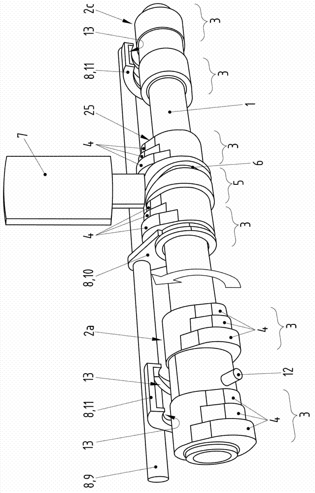
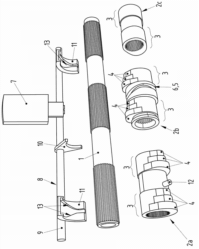
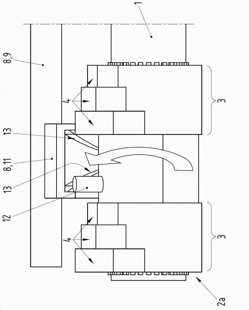
[0024] Figure 1 to Figure 8 Various views and details of a first variant according to the invention of a valve drive of an internal combustion engine are shown.

[0025] then Figure 1 to Figure 8 The valve drive comprises a camshaft 1 which is supported via a not shown camshaft bearing on a not shown internal combustion engine cylinder head. A cylinder head of this type can consist of a cylinder head lower part and a camshaft housing, wherein the cylinder head lower part and the camshaft housing can also be embodied in one piece.

[0026] exist Figure 1 to Figure 8 The camshaft 1 shown in is preferably an intake camshaft, which is used to control the likewise not shown intake valves of the internal combustion engine with a roller lever not shown. There is a not shown exhaust camshaft for controlling the not shown internal combustion engine exhaust valves. The intake and exhaust valves of an internal combustion engine are the gas exchange valves of the internal combustio...


PUM


Abstract

The invention relates to an internal combustion engine and a valve drive unit thereof. The internal combustion engine comprises a plurality of cylinders. At least one cam shaft is rotatably supported in order to operate ventilating valves of the cylinders of a cylinder set, and one sliding cam allowing axial sliding is arranged on the cam shaft corresponding to each cylinder. A common actuator (7) is provided for all the sliding cams (2a, 2b, 2c) so that the sliding cams (2a, 2b, 2c) supported on the cam shaft (1) in an axially slidable manner can slide axially.

Description

technical field [0001] The invention relates to an internal combustion engine. Furthermore, the invention relates to a valve drive for an internal combustion engine. Background technique [0002] In internal combustion engines, variable valve drives are used in order to optimize the charge movement in the combustion chamber, whereby different valve lifts can be set at the gas exchange valves of the internal combustion engine. A valve drive is known from DE 19611641 C1, whereby the gas exchange valve can be actuated with various lift curves. Furthermore, a sliding cam is supported on the camshaft in a non-rotatable but axially slidable manner via cam tracks, the sliding cam has a lift profile into which a pin-shaped actuator fits in order to generate the Axial sliding of sliding cams. Through the axial sliding of the sliding cam, different valve lifts can be set at the corresponding gas exchange valves. After its axial sliding relative to the camshaft, the sliding cam can...

Claims


Application Information

Patent Timeline
Patent Type & Authority Applications(China)
IPC IPC(8): F01L1/053F01L13/00
CPCF01L1/053F01L2001/0473F01L2013/0052
Inventor G·沃格勒赞格
Owner DR ING H C F PORSCHE AG
Learn More