
Method for treatment of heavy hydrocarbon raw material with up-flow reactor

A technology for reactors and hydrogenation reactors, applied in chemical instruments and methods, refined hydrocarbon oil, chemical/physical processes, etc., can solve the problems of catalyst back-mixing, cumbersome loading and unloading of different types, etc., and achieve high hydrogenation activity and good Reaction channel, effect of good ability to demetallize impurities

Active Publication Date: 2019-06-18
CHINA PETROLEUM & CHEM CORP +1
View PDF5 Cites 0 Cited by
  • Summary
  • Abstract
  • Description
  • Claims
  • Application Information

AI Technical Summary

Problems solved by technology

Moreover, the present invention applies the single type of catalyst to the upflow reactor, which overcomes the problems of many types of catalysts in the current upflow reactor, cumbersome loading and unloading, and back-mixing of different types of catalysts.

Method used


Image

  • Method for treatment of heavy hydrocarbon raw material with up-flow reactor
  • Method for treatment of heavy hydrocarbon raw material with up-flow reactor

Examples


Embodiment 1

[0045] Take by weighing silicon oxide content and be that the water glass 1000g of 30wt% adds in the beaker, start stirring device, slowly add mass concentration in the beaker and be the nitric acid solution 376g of 62%, make the pH value of water glass solution in the beaker be 2.0, then add to above-mentioned Add 416.7g pseudo-boehmite to the solution (properties are as follows: pore volume 0.985mL / g, specific surface area 313m 2 / g, dry basis is 72wt%), after stirring evenly, add 83g of curing agent urea, after the urea is completely dissolved, add deionized water, so that the material in the beaker is a paste with a certain fluidity, and silicon dioxide and oxide The solids content is 33% based on aluminum.

[0046] Press the above paste material into the pre-prepared rigid body mold with a spherical cavity and mandrel. After the paste material fills the entire cavity, insert the last short mandrel. When the short mandrel touches the first core Axle rear fixed. Two verti...

Embodiment 2

[0050] The preparation process is as in Example 1, except that the mold is replaced, the diameter of the cavity and the mandrel is increased, and the prepared catalyst carrier B and catalyst B C The properties are shown in Table 1. Wherein, the outer diameter of the obtained catalyst carrier B is about 7.5 mm, and the diameter of the through holes is about 3.8 mm.

Embodiment 3

[0052] The preparation process is as in Example 1, except that the nitric acid solution 373g and 53g nickel nitrate with a mass concentration of 62% will be slowly added into the beaker, and the solid content in terms of silicon dioxide and aluminum oxide is 35%, the prepared catalyst carrier C and Catalyst C C , whose properties are shown in Table 1. Wherein, the outer diameter of the obtained catalyst carrier C is about 5.5 mm, and the diameter of the through holes is about 2.5 mm.


PUM

PropertyMeasurementUnit
specific surface areaaaaaaaaaaa
diameteraaaaaaaaaa
specific surface areaaaaaaaaaaa

Abstract

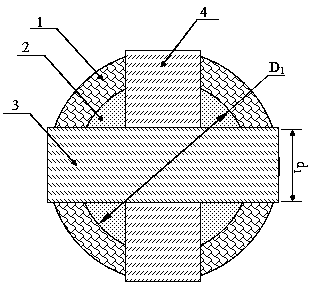
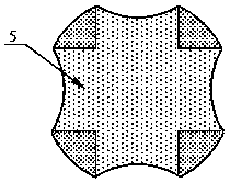
The invention discloses a method for treatment of a heavy hydrocarbon raw material with an up-flow reactor. The method includes adopting at least one up-flow hydrogenation reactor, in which at least two catalyst beds are disposed, and each catalyst bed adopts a same hydrotreating catalyst; the carrier of the hydrotreating catalyst is a sphere with two through channels, the outer diameter of the sphere is 5.0-8.0mm, the two channels are both through-holes that pass through the center of the sphere and are perpendicular to each other, and the diameter of the through-holes is 30%-60% of the outerdiameter of the sphere. The method provided by the invention adopts the specific catalyst, which has good hydrogenation performance and demetalization and metal accommodation capacity, at the same time has certain desulfurization and carbon residue and asphaltene conversion capability, and has long service life. Moreover, the method provided by the invention overcomes the problems of large catalyst variety, tedious loading and unloading, backmixing of different catalysts and the like in current up-flow reactors.

Description

technical field [0001] The invention relates to a technology for hydrogenation treatment of hydrocarbon raw materials, in particular to a method for treating heavy hydrocarbon raw materials with an upflow reactor. Background technique [0002] As crude oil becomes heavier and worse, more and more heavy oil and residual oil need to be processed. The processing of heavy oil and residual oil not only needs to be cracked into products with low boiling points, such as naphtha, middle distillate oil and vacuum gas oil, but also to increase their hydrogen-carbon ratio, which requires decarbonization or Hydrogenation method to achieve. Among them, the decarbonization process includes coking, solvent deasphalting, heavy oil catalytic cracking, etc.; the hydrogenation process includes hydrocracking, hydrofining, hydrotreating, etc. The hydrogenation process can not only hydrogenate and convert residual oil, improve the yield of liquid products, but also remove heteroatoms in it, and...

Claims


Application Information

Patent Timeline
Patent Type & Authority Applications(China)
IPC IPC(8): C10G45/14C10G45/08B01J27/19B01J35/08
Inventor 刘铁斌耿新国
Owner CHINA PETROLEUM & CHEM CORP
Learn More