
Device for performing puncture biopsy under laser guide

A puncture biopsy and laser-guided technology, applied in the field of medical devices, can solve problems such as lack of guidance, puncture deviation, danger, etc., and achieve the effect of ensuring accuracy and preventing deviation

Pending Publication Date: 2019-06-18
成都真实维度科技有限公司 +1
View PDF0 Cites 2 Cited by
  • Summary
  • Abstract
  • Description
  • Claims
  • Application Information

AI Technical Summary

Problems solved by technology

[0003] The diagnosis of many diseases requires pathological section examination. In order to obtain pathological tissue, especially the pathological tissue hidden inside the body, puncture sampling is required. At present, there is a needle aspiration puncture method, which is to puncture the puncture needle into the mass and then use a syringe The principle of negative pressure suction is to obtain a small amount of pathological tissue or interstitial fluid for diagnosis. However, due to the tissue toughness of pathological living tissues, it is often difficult to aspirate the tissue or the interstitial fluid obtained cannot be used for pathological diagnosis, and the existing puncture The process lacks guidance and requires medical staff to locate the puncture position through experience. There is a possibility of deviation in puncture, and the depth of puncture cannot be accurately grasped.
For beginners or inexperienced medical personnel, the problem of puncture deviation often occurs during use, which damages the tissue and is very dangerous.

Method used


Image

  • Device for performing puncture biopsy under laser guide
  • Device for performing puncture biopsy under laser guide
  • Device for performing puncture biopsy under laser guide

Examples


Embodiment 1

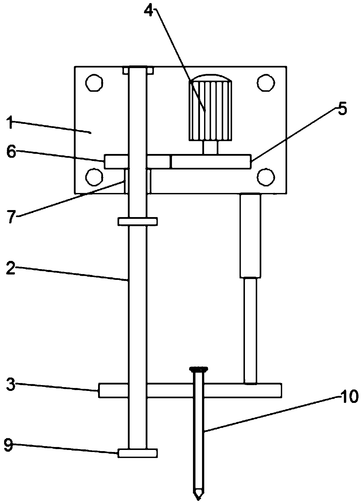
[0028] like figure 1 , 2 As shown, a device for performing a needle biopsy guided by a laser includes a propulsion device and a needle biopsy device 10, and the needle biopsy device 10 is fixedly connected to the propulsion device;

[0029] The propulsion device includes a drive motor 4, a drive rod 2 and a fixed plate 3, the drive rod 2 is connected to the drive motor 4, and the fixed plate 3 is screwed on the drive rod 2;

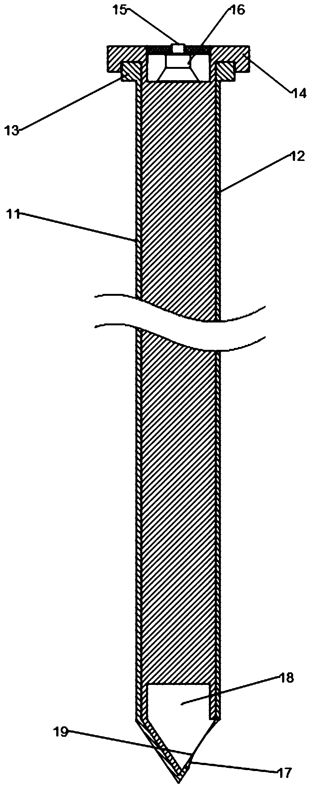
[0030] The puncture biopsy device 10 includes a puncture needle cover 11 and a sampler 12, the puncture needle cover 11 is fixed on the fixed plate 3, the sampler 12 is slidably connected in the puncture needle cover 11, the puncture needle cover 11 The front end is a conical needle, and the side of the conical needle is provided with a sampling hole 17, and the front end of the sampler 12 is a conical head, and the front end of the sampler 12 is provided with a sampling hole 18, and the sampling hole 18 A cutting piece 19 is provided at the orifice of ...

Embodiment 2

[0033] As a preferred technical solution of the present invention, on the basis of Example 1, the taper of the conical head is consistent with the taper of the conical needle, the aperture of the sampling hole 18 is equal to or greater than the aperture of the sampling hole 17, the The blade of cutting sheet 19 coincides with the generatrix of the tapered needle cone. The taper of the conical head is set to be consistent with the taper of the conical needle to ensure the tightness of the sampler 12 and the puncture needle cover 11, which is convenient for cutting the pathological tissue. In the sampling hole 18, in order to prevent that the diameter of the sampling hole 18 is too small to affect the pathological tissue, the inlet aperture of the sampling hole 18 is set to be equal to or greater than the aperture of the sampling hole 17, and the blade of the cutting piece 19 is connected to the conical surface of the tapered needle. When the cutting piece 19 is cutting the path...

Embodiment 3

[0036] As a preferred technical solution of the present invention, on the basis of Example 1, the rear end of the puncture needle cover 11 is provided with a positioning plate 13, and the rear end of the sampler 12 is provided with a positioning sleeve 14, and the positioning sleeve 14 Transition fit with positioning disc 13. In order to ensure the accuracy of sampling, the puncture biopsy device 10 needs to be positioned. Since the puncture needle cover 11 of the puncture biopsy device 10 is fixed on the fixed plate 3, and the sampler 12 is slidably connected in the puncture needle cover 11, it is necessary to The sampler 12 is positioned to ensure accurate cutting. By being provided with a positioning disk 13 at the rear end of the puncture needle cover 11, and a positioning sleeve 14 is provided at the rear end of the sampler 12, the positioning sleeve 14 is sleeved on the positioning disk 13, and the positioning sleeve 14 is connected to the positioning disk 13. There is ...


PUM


Abstract

The invention belongs to the technical field of medical devices and particularly relates to a device for performing puncture biopsy under laser guide. The device comprises a propelling device and a puncture biopsy device, wherein the puncture biopsy device is fixedly connected to the propelling device; the puncture biopsy device comprises a puncture needle sheath and a sampler, a sampling hole isformed in the front end of the puncture needle sheath, a cutting disc is arranged at the orifice of the sampling hole, a laser sensor and a prompter are arranged at the rear end of the sampler, and the central line of the laser sensor is colinear with the axis of a conical needle head. By means of the propelling device and the puncture biopsy device, the propelling device is used for pushing the puncture biopsy device to move forward to reach the pathological tissue position, the puncture biopsy device is used for cutting down a small piece of pathological tissue and taking out the pathological tissue to be used for follow-up section examination; the laser sensor and the prompter are used for realizing laser guide to prevent skewing of puncture and guarantee puncture accuracy.

Description

technical field [0001] The invention belongs to the technical field of medical devices, and in particular relates to a device for puncture biopsy guided by laser. Background technique [0002] Biopsy (biopsy) referred to as "biopsy", also known as surgical pathological examination, referred to as "external examination"; refers to the need for diagnosis and treatment, to remove diseased tissue from the patient's body, such as cutting, forceps or puncture, for pathological examination. Check the technique. It is the most important part of diagnostic pathology. It can make a clear histopathological diagnosis for the vast majority of cases submitted for inspection, and it is used as the final clinical diagnosis. [0003] The diagnosis of many diseases requires pathological section examination. In order to obtain pathological tissue, especially the pathological tissue hidden inside the body, puncture sampling is required. At present, there is a needle aspiration puncture method,...

Claims


Application Information

Patent Timeline
IPC IPC(8): A61B10/02A61B17/34A61B90/13
Inventor 伍建林曲飞寰于晶张清范鸿禹伍远航王亮张黎川李建新
Owner 成都真实维度科技有限公司
Learn More