A photographic device that can automatically clean up the camera

A photographic device and automatic cleaning technology, applied to the cleaning method using gas flow, image communication, cleaning method and utensils, etc., can solve the problems affecting the high-quality cleaning of the wiping cloth, the rapid adsorption of dust, and the ineffective cleaning, etc., to achieve Reduce manual repeated wiping action, easy to install and use, soft and delicate material effect

Active Publication Date: 2021-03-30
CHANGCHUN NORMAL UNIVERSITY
View PDF6 Cites 0 Cited by
  • Summary
  • Abstract
  • Description
  • Claims
  • Application Information

AI Technical Summary

Problems solved by technology

In the initial cleaning process, the blower is used to remove large particles of dust and impurities, and then a large amount of clean water is used for one-time flushing. Most of the clean water does not really participate in the cleaning and flushing. At the same time, the clean water will eventually remain on the lens. At the same time, it will also carry or re-absorb dust residues. Adsorbing water stains will affect the wiping of the cloth and affect the high-quality cleaning of the final wipe. If the water stains are removed by wind blowing, it will cause rapid adsorption of dust in the air, and there are still problems
At the same time, in general wiping products and wiping actions, the contact wiping effect on the boundary between the lens sheet and the lens housing is poor. Due to the curvature and the deformation limitation of the wiping product, the initial wiping can no longer effectively clean the boundary.

Method used


Image

  • A photographic device that can automatically clean up the camera
  • A photographic device that can automatically clean up the camera
  • A photographic device that can automatically clean up the camera

Examples


Embodiment Construction

[0027] The present invention will be further described in detail below in conjunction with the accompanying drawings and specific embodiments.

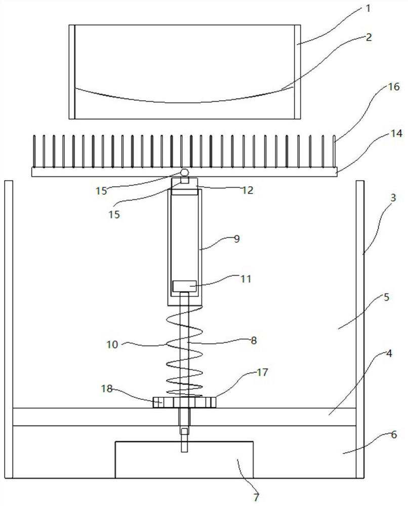
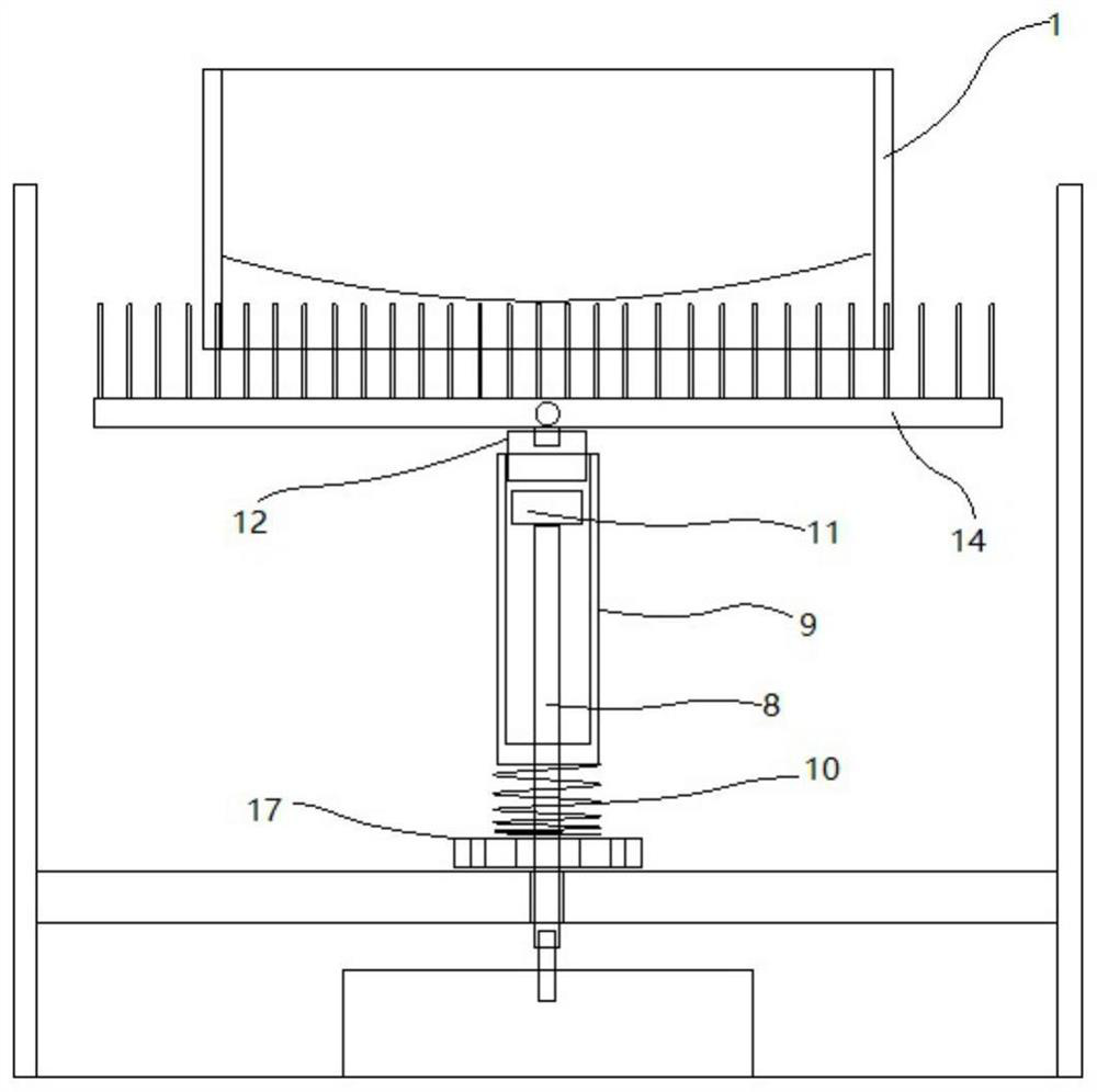
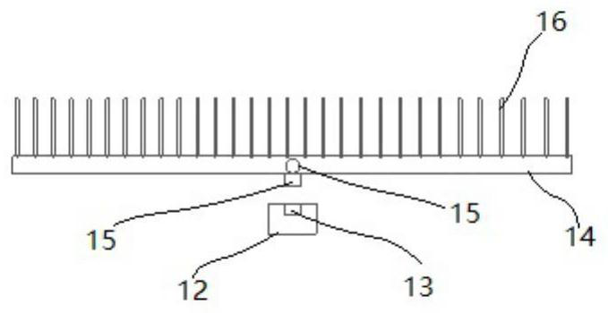
[0028] Such as Figure 1-8 As shown, a photographic device capable of automatically cleaning the camera includes a camera lens; the camera lens includes a casing 1 and a lens sheet 2; it is characterized in that: the casing 1 is fitted with a cleaning device; the cleaning device includes a casing 1 The carrying barrel 3 is connected to the set; the lower part of the carrying barrel 3 is provided with a partition 4; the partition 4 divides the interior of the carrying barrel 3 into upper and lower parts, the upper part is the cleaning chamber 5, and the lower part is the installation chamber 6; the middle part of the installation chamber 6 is installed There is a driving motor 7; the output end of the driving motor 7 is connected with a vertical transmission rod 8; the transmission rod 8 seals and passes through the partition plate 4 a...


PUM


Abstract

The invention discloses a photographic device capable of automatically cleaning a camera, and relates to the technical field of photographic equipment. The camera comprises a camera lens. The camera lens comprises a shell and a lens sheet. The shell is sleeved and matched with a cleaning device. The cleaning device comprises a bearing barrel connected with the shell in a sleeved mode. The upper part is a cleaning cavity, and the lower part is a mounting cavity. A driving motor is mounted in the middle in the mounting cavity. In the cleaning cavity, the upper part of the transmission rod is slidably connected with a sleeve. The lower end of the sleeve is fixedly connected with a pressure spring. The top end of the transmission rod is fixedly connected with a transmission block in insertionfit with the interior of the sleeve. An inserting hole is formed in the upper end of the cover plate. A brush plate is inserted into the insertion hole. Bristles are uniformly distributed at the upperend of the brush plate. The cleaning cavity is filled with shear thickening fluid. And when the pressure spring is not compressed, the brush plate is higher than the upper end surface of the bearingbarrel. The method has the beneficial effects that the surface of the lens is cleaned in an attached manner by utilizing the characteristics of the shear thickening fluid, and residues on the surfaceof the lens after cleaning can be reduced.

Description

technical field [0001] The invention relates to the technical field of photography and imaging equipment. Background technique [0002] In photographic camera devices, the surface of the lens must be kept clean and transparent, so a cleaning device is required in the photographic device. A soft and fine wiping cloth is a must for the cleaning device, and it can achieve the final cleaning of the lens with high quality. However, when cleaning, it cannot be cleaned directly with the wiping cloth. It needs to be cleaned in the initial stage to reduce the wear of the wiping cloth and the lens. Improve the use quality of wipes. In the initial cleaning process, the blower is used to remove large particles of dust and impurities, and then a large amount of clean water is used for one-time flushing. Most of the clean water does not really participate in the cleaning and flushing. At the same time, the clean water will eventually remain on the lens. At the same time, it will also ca...

Claims


Application Information

Patent Timeline
Patent Type & Authority Patents(China)
IPC IPC(8): H04N5/225B08B5/02B08B3/08B08B1/04
Inventor 杜丹冰尚亚丽
Owner CHANGCHUN NORMAL UNIVERSITY
Why Eureka
Try Eureka