
Annular cutting device for processing of automobile harness

An automotive wiring harness and loop cutting technology, applied in the direction of disassembling/armored cable equipment, etc., can solve the problems of high labor intensity, low wire stripping efficiency, manual wire stripping, etc., to save labor, fast and efficient loop cutting work, work Efficient effect

Inactive Publication Date: 2019-06-14
MAANSHAN HETIAN ELECTRONICS INTELLIGENCE CONTROL SYST CO LTD
View PDF7 Cites 8 Cited by
  • Summary
  • Abstract
  • Description
  • Claims
  • Application Information

AI Technical Summary

Problems solved by technology

[0004] The purpose of the present invention is to solve the problem that in the prior art, the stripping of the vehicle wiring harness is manually performed by manual operation of wire strippers. Before stripping the wires, it is usually necessary to cut them manually with a knife. The phenomenon of internal scratches, and after cutting, manual stripping is required, the operation is complicated, the labor intensity is high, the stripping quality is poor, and the stripping efficiency is low, and a ring cutting device for automobile wire harness processing is proposed.

Method used


Image

  • Annular cutting device for processing of automobile harness
  • Annular cutting device for processing of automobile harness
  • Annular cutting device for processing of automobile harness

Examples


Embodiment Construction

[0026] The following will clearly and completely describe the technical solutions in the embodiments of the present invention with reference to the accompanying drawings in the embodiments of the present invention. Obviously, the described embodiments are only some, not all, embodiments of the present invention.

[0027] In describing the present invention, it should be understood that the terms "upper", "lower", "front", "rear", "left", "right", "top", "bottom", "inner", " The orientation or positional relationship indicated by "outside", etc. is based on the orientation or positional relationship shown in the drawings, and is only for the convenience of describing the present invention and simplifying the description, rather than indicating or implying that the referred device or element must have a specific orientation, so as to Specific orientation configurations and operations, therefore, are not to be construed as limitations on the invention.

[0028] refer to Figure ...


PUM


Abstract

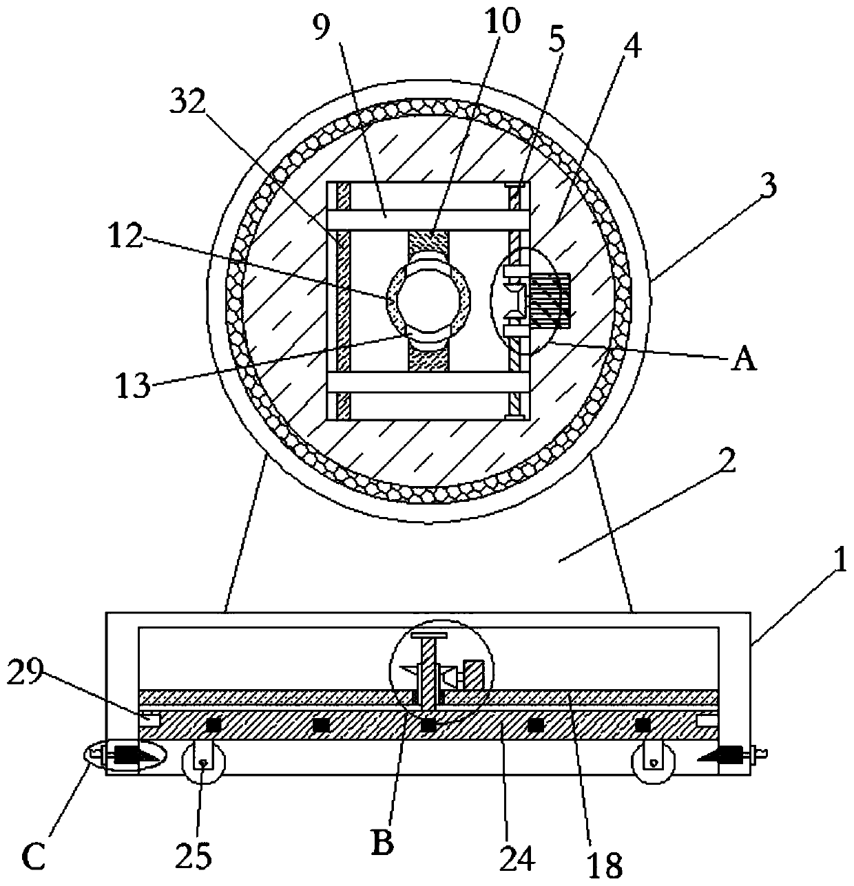
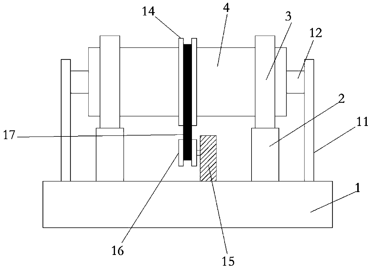
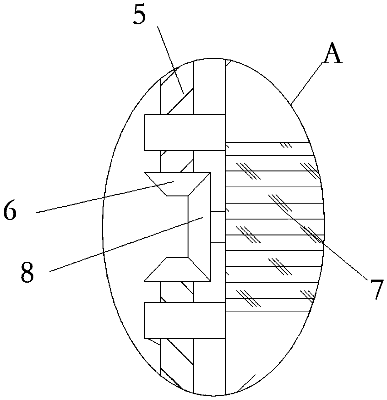
The invention relates to the technical field of harness processing, and discloses an annular cutting device for processing of an automobile harness. The annular cutting device comprises a base, wherein two support seats are symmetrically and fixedly connected with an upper end of the base in a frontward-rearward way, a ball bearing is fixedly connected with an upper end of each support seat, the same fixed pipe rotatably sleeve the two ball bearings, a rectangular structure is arranged in the fixed pipe, screw rods are rotatably connected with inner walls of sides, opposite to each other in anupward-downward way, of the fixed pipe, first driven bevel gears are fixedly connected with ends, opposite to each other, of the two screw rods, a first motor is fixedly embedded onto an inner wall of the fixed pipe, two first driving bevel gears are fixedly connected with an output shaft of the first motor and are engaged with the first driven gears, press plates are in threaded connection withrod walls of the screw rods, and cutters are fixedly connected with side walls of sides, opposite to each other, of the two press plates. By the annular cutting device, annular cutting operation of acable can be rapidly and efficiently performed, the working efficiency is high, and the labor is saved.

Description

technical field [0001] The invention relates to the technical field of wire harness processing, in particular to a ring cutting device for automobile wire harness processing. Background technique [0002] The automobile wiring harness is the main body of the automobile circuit network, and there is no automobile circuit without the wiring harness. The wire harness refers to the contact terminal (connector) punched from copper and the wire and cable after crimping, and then plastic insulator or metal shell on the outside, and then bundled with wire harness to form a connected circuit component. The wiring harness industry chain includes wire and cable, connectors, processing equipment, wiring harness manufacturing and downstream application industries. The wiring harness is widely used and can be used in automobiles, household appliances, computers and communication equipment, various electronic instruments, etc. The body wiring harness connects the entire body , the general...

Claims


Application Information

Patent Timeline
Patent Type & Authority Applications(China)
IPC IPC(8): H02G1/12
Inventor 沈抗勇宗寒胡鉴涛
Owner MAANSHAN HETIAN ELECTRONICS INTELLIGENCE CONTROL SYST CO LTD
Learn More