Coal mill with dustproof function for thermal power plant

A technology for thermal power plants and coal mills, applied in the field of coal mills, can solve the problems of high temperature and large amount of dust, and achieve the effects of less oxygen content, difficult pulverized coal combustion, and less oxygen content in the fuselage.

Inactive Publication Date: 2019-06-11
陕西冠霖电子科技有限公司
View PDF0 Cites 0 Cited by
  • Summary
  • Abstract
  • Description
  • Claims
  • Application Information

AI Technical Summary

Problems solved by technology

[0003] The purpose of the present invention is to solve the shortcomings of large amount of dust and high temperature in the prior art, and propose a coal pulverizer for thermal power plants with dust-proof function

Method used


Image

  • Coal mill with dustproof function for thermal power plant

Examples


Embodiment Construction

[0013] The following will clearly and completely describe the technical solutions in the embodiments of the present invention with reference to the accompanying drawings in the embodiments of the present invention. Obviously, the described embodiments are only some, not all, embodiments of the present invention.

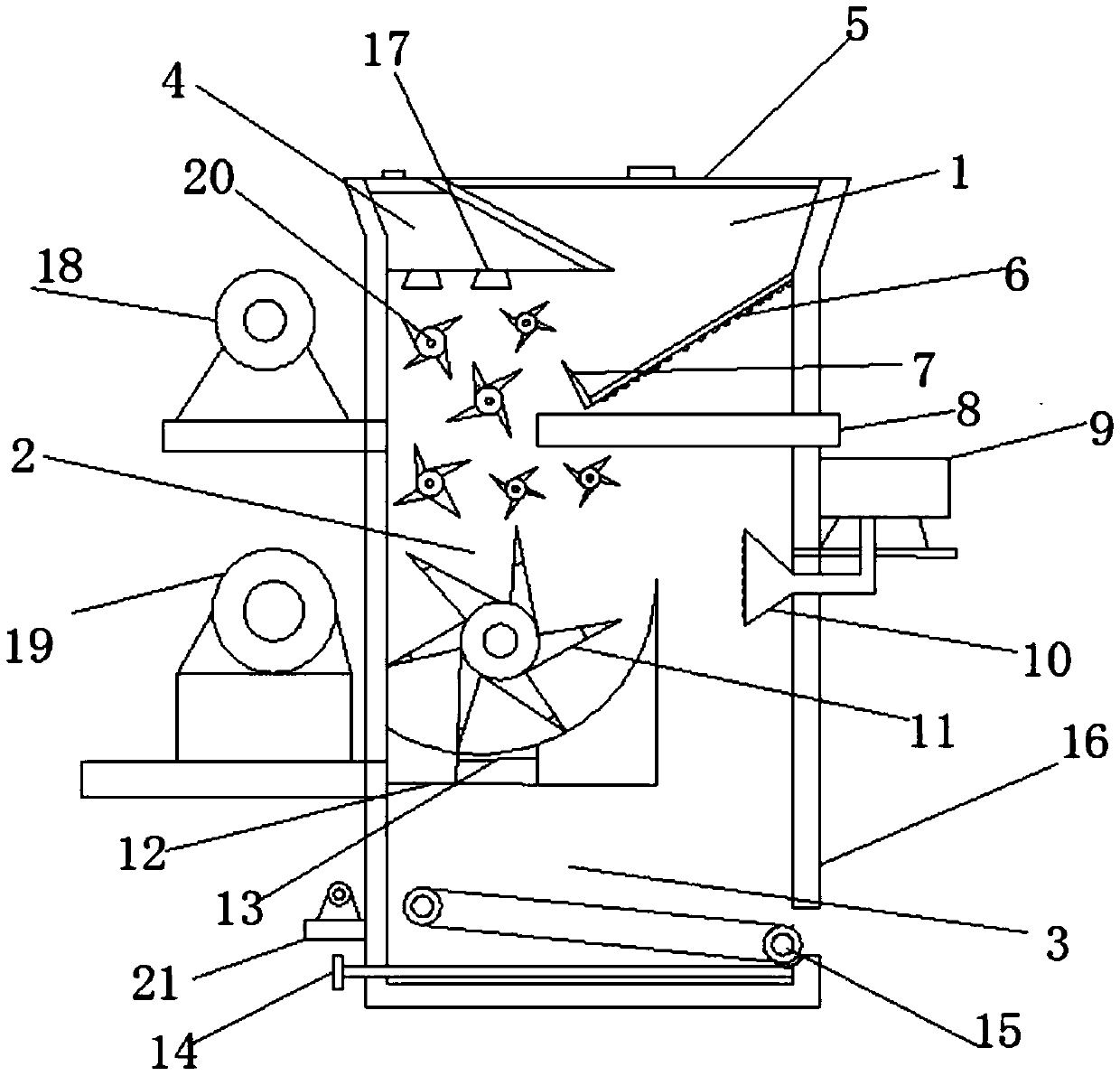
[0014] refer to figure 1 , a coal mill with dust-proof function for thermal power plants, including a fuselage 16, a feed bin 1, a spray chamber 4, a crushing bin 20 and a discharge bin 3, and the inside of the fuselage 16 is respectively equipped with an inlet and outlet from top to bottom. Feed bin 1, spray chamber 4, crushing bin 20, and discharge bin 3, top cover 5 is provided on feed bin 1, sieve plate 6 is provided on feed bin 1, and sieve plate 6 is obliquely fixed on machine body 16 , the sieve plate 6 plays the role of dust removal for the first time, the other end of the sieve plate 6 is provided with a baffle 7, the baffle 7 is a rubber baffle and the uppe...


PUM


Abstract

The invention relates to the technical field of coal mills, in particular to a coal mill with a dustproof function for a thermal power plant. The coal mill comprises a machine body, a feeding bin, a spraying chamber, a crushing bin and a discharging bin, wherein the feeding bin, the spraying chamber, the crushing bin and the discharging bin are arranged in the machine body from top to bottom, wherein a top cover is arranged on the feeding bin, a sieve plate is arranged on the feeding bin, a baffle plate is arranged at the other end of the sieve plate, a dust collecting box is arranged on the lower side of the sieve plate, the spraying chamber is arranged at the top of the machine body, second nozzles are arranged in the spraying chamber, the crushing chamber is arranged on the lower side of the spraying chamber, a first motor and a second motor are arranged on the outer side of the machine body, a plurality of second crushing rollers are arranged in the crushing chamber, a first crushing roller is arranged on the lower side of the second crushing rollers, a baffle plate table is arranged at the lower end of the first crushing roller, a filter screen is arranged in the middle of thebaffle plate table, a nitrogen liquid chamber is arranged on the machine body, a first nozzle is arranged at the other end of the nitrogen liquid chamber, a discharging chamber is arranged below thefilter screen, wherein belt rotating shafts are arranged on the discharging chamber, a discharging hole is formed in the side, far away from a third motor, of the machine body, and a collecting box isarranged at the bottom of the machine body.

Description

technical field [0001] The invention relates to the technical field of coal pulverizers, in particular to a coal pulverizer for a thermal power plant with a dust-proof function. Background technique [0002] The existing coal mills are difficult to control the size of the pulverized coal, which leads to the uneven size of the pulverized coal. The existing pulverizers basically grind the pulverized coal at one time, resulting in a poor effect of the pulverized coal. . Moreover, the usually used coal mills have high requirements for temperature and oxygen content. If the temperature of the coal mill is too high, the pulverized coal will burn and cause a fire, and the pulverized coal dust will float around and affect the environment, which is harmful to the work. People's bodies are affected. Contents of the invention [0003] The purpose of the present invention is to solve the shortcomings of large amount of dust and high temperature in the prior art, and propose a coal p...

Claims


Application Information

Patent Timeline
Patent Type & Authority Applications(China)
IPC IPC(8): B02C18/14B02C18/16B02C23/04B02C23/16B02C23/40
Inventor 李明潮
Owner 陕西冠霖电子科技有限公司
Why Eureka
Try Eureka