Cable pulling device used in electric power engineering

A technology of electric power engineering and cables, which is applied in the direction of cable laying equipment, etc., can solve problems such as cutting, cable pullback, and unfavorable cable laying, so as to ensure effective laying and avoid damage

Inactive Publication Date: 2019-06-07
常熟虞星光电科技有限公司
View PDF0 Cites 1 Cited by
  • Summary
  • Abstract
  • Description
  • Claims
  • Application Information

AI Technical Summary

Problems solved by technology

[0002] In the current traditional cable laying construction process, the cable is generally delivered to the cable well by manpower. The labor intensity of manpower pulling the cable is high, and human physical strength limits the speed of pulling the cable, and the work efficiency is very low. After the cable winch stops, On the one hand, the cable winch may rotate and take up the wire under the action of unintentional external force, which will cause the cable being laid in the cable shaft to pull back, which is not conducive to the smooth progress of cable laying, thus affecting the construction progress of cable laying; on the other hand, The larger external force generated due to various reasons pulls the cable that has been pulled out, or the heavier and angular weight falls from above to the suspended part of the cable that has been pulled out. At this time, the external force or Heavy objects impact the cables; large external forces instantly straighten the cables and cause damage to the cables or the edges and corners of falling heavy objects may cut the cable sheath, so that the effective laying of cables and the safety of power construction cannot be guaranteed.

Method used


Image

  • Cable pulling device used in electric power engineering
  • Cable pulling device used in electric power engineering
  • Cable pulling device used in electric power engineering

Examples


Embodiment Construction

[0037] The accompanying drawings are all schematic diagrams of the implementation of the present invention, so as to understand the principle of structural operation. The specific product structure and proportional size can be determined according to the use environment and conventional technology.

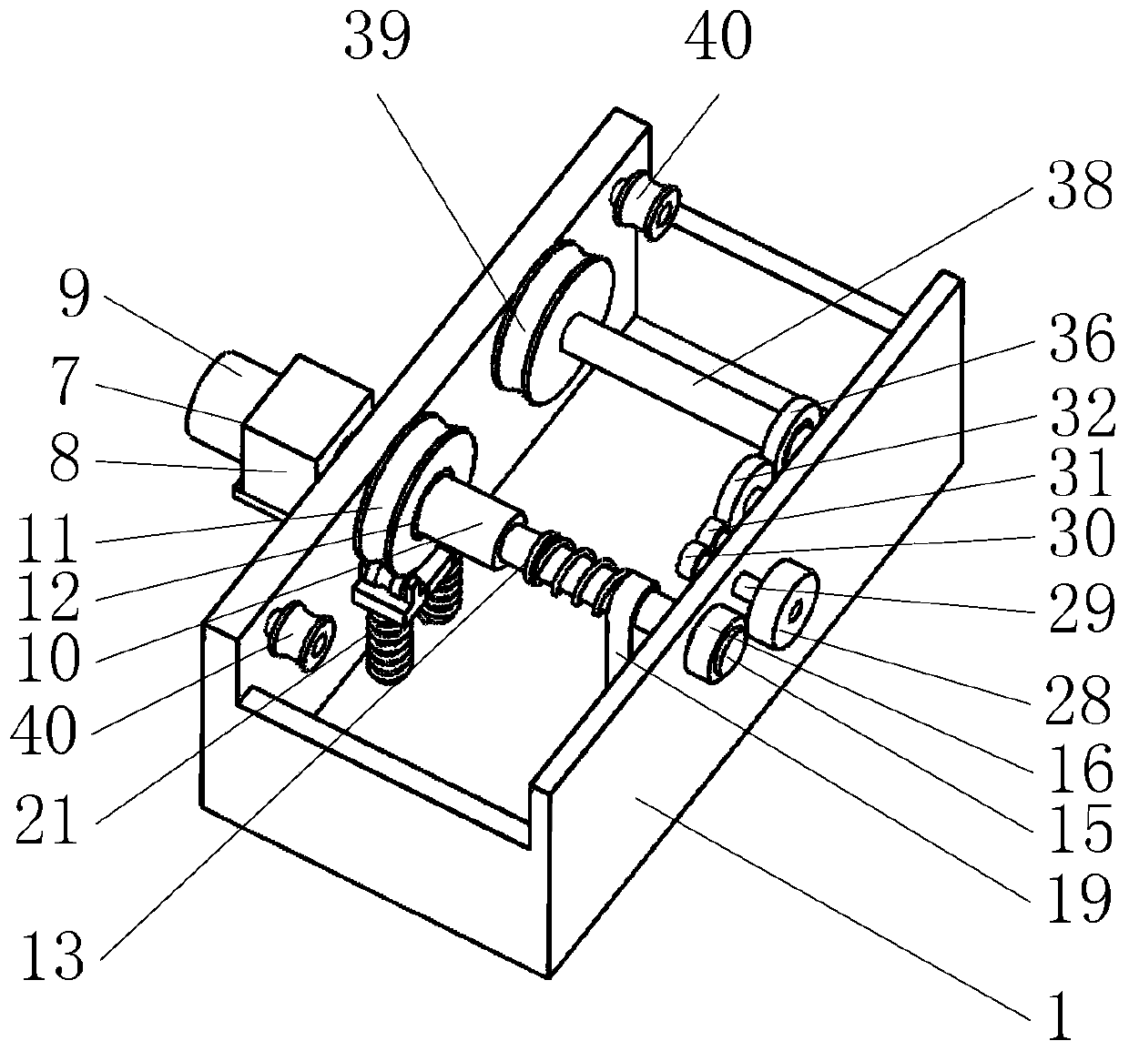
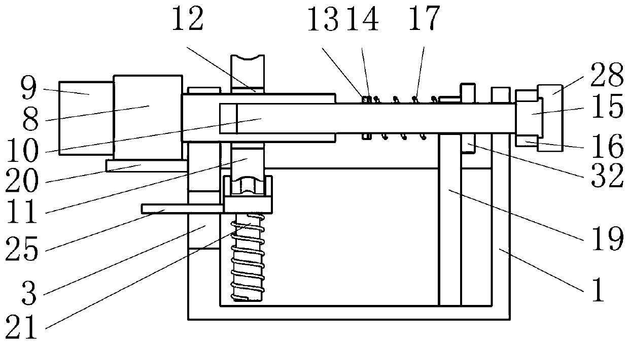
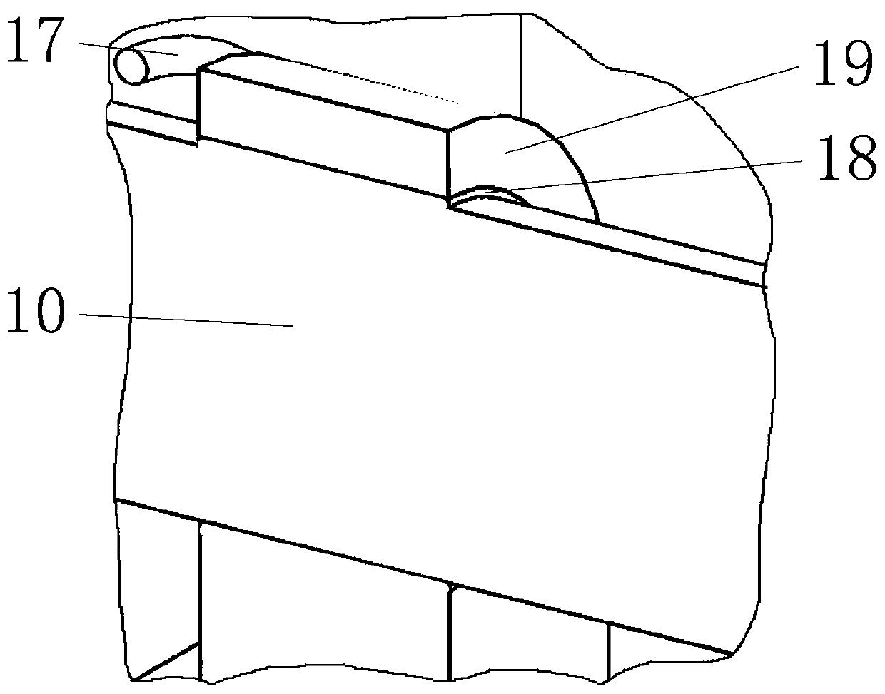
[0038] Such as figure 1 As shown, it includes a housing 1, an electric drive module 7, a telescopic shaft 10, a first roller 11, a first one-way clutch 12, a torque limiter 15, a first friction wheel 16, a first return spring 17, a fixed block 19, Compression mechanism 21, second friction wheel 28, first shaft 29, first gear 30, transmission gear 31, second gear 32, second shaft 34, scroll spring 35, third gear 36, second one-way clutch 37, the third shaft 38, the second roller 39, the third roller 40, wherein as figure 2 , 6 As shown, the telescopic outer sleeve of the telescopic shaft 10 cooperates with the first shaft hole 2 bearings on the side of the housing 1, and the te...


PUM


Abstract

The invention belongs to the field of electric power construction, and particularly relates to a cable pulling device used in electric power engineering. The cable pulling device used in the electricpower engineering comprises a telescopic shaft, a torque limiter, a hold-down mechanism and the like, and a telescopic outer sleeve of the telescopic shaft is matched with a first axle hole bearing onthe side surface of a shell; according to the cable pulling device used in the electric power engineering, after a motor in an dynamic drive module stops operating, a cable cannot be released out from a cable winch, two fourth rollers can extrude the cable, friction between the fourth rollers and the cable enables the cable to be not prone to being pulled, and continuous performing of the construction is not affected; according to a first roller, after the motor stops, a volute spiral spring releases energy so as to enable a second roller to continuously rotate at some angles in the rotationdirection of the second roller, and a certain cable allowance is reserved for cable construction; and the second roller pulls out a part of the cable from the cable winch, the cable between the firstroller and the second roller is in a loosening state, damage of corner angles on fallen heavy objects to the outer skin of the cable is avoided, and effective pavement and electric power constructionsafety operation are ensured.

Description

technical field [0001] The invention belongs to the field of electric power construction, in particular to a cable pulling device used in electric power engineering. Background technique [0002] In the current traditional cable laying construction process, the cable is generally delivered to the cable well by manpower. The labor intensity of manpower pulling the cable is high, and human physical strength limits the speed of pulling the cable, and the work efficiency is very low. After the cable winch stops, On the one hand, the cable winch may rotate and take up the wire under the action of unintentional external force, which will cause the cable being laid in the cable shaft to pull back, which is not conducive to the smooth progress of cable laying, thus affecting the construction progress of cable laying; on the other hand, The larger external force generated due to various reasons pulls the cable that has been pulled out, or the heavier and angular weight falls from abo...

Claims


Application Information

Patent Timeline
Patent Type & Authority Applications(China)
IPC IPC(8): H02G1/06
Inventor 龚利芬戴丽芬
Owner 常熟虞星光电科技有限公司
Why Eureka
Try Eureka