Light source module and light-emitting lamp

A technology of light source module and light-emitting lamp, which is applied in the direction of light source, light source fixation, and semiconductor devices of light-emitting elements, etc. It can solve the problems of increasing the distance between LED lamp beads, poor bonding, peeling off of circuit boards and lamp bodies, etc., and achieves increased Large light output angle and radiation three-dimensional space angle, improve the overall structural stability, and improve the effect of thermal management ability

Pending Publication Date: 2019-06-07
国瓷赛创电气(铜陵)有限公司
View PDF7 Cites 0 Cited by
  • Summary
  • Abstract
  • Description
  • Claims
  • Application Information

AI Technical Summary

Problems solved by technology

Poor heat dissipation, poor heat dissipation treatment is easy to light decay, affecting the service life of lights
[0004] In addition, the various parts of the above structure are not mechanically fixed, for example, between the circuit board and the lamp body, if they work in a high temperature environment for a long time, the colloid will age, and there will be peeling between the circuit board and the lamp body (the adhesion is not strong) Phenomenon; not suitable for long-term lighting, resulting in uneven product quality
[0005] Secondly, the LED light-emitting lamp with the above-mentioned structure also performs poorly in terms of light pattern design. For example, the circuit board with LED lamp beads on both sides is fixed on the lamp body by thermally conductive silicone grease, which increases the size of the LED lamp beads on both sides. spacing between
Compared with the traditional halogen lamp, it can be equivalent to a line light source, but the structure of this traditional LED light-emitting lamp cannot be equivalent, and it cannot directly replace the traditional halogen lamp.
This LED lighting structure increases the difficulty of light distribution and limits the use of LED lighting
[0006] In addition, there are also problems such as poor maintenance performance, a certain gap between the appearance of the lamp and the bulbs we are used to, and the acceptance of people is challenged.

Method used


Image

  • Light source module and light-emitting lamp
  • Light source module and light-emitting lamp
  • Light source module and light-emitting lamp

Examples


Embodiment Construction

[0043] In order to make the content of the present invention clearer and easier to understand, the content of the present invention will be further described below in conjunction with the accompanying drawings. Of course, the present invention is not limited to this specific embodiment, and general replacements known to those skilled in the art are also covered within the protection scope of the present invention.

[0044] The following is attached Figure 1~8 The present invention will be described in further detail with specific examples. It should be noted that the drawings are all in a very simplified form, using imprecise scales, and are only used to facilitate and clearly achieve the purpose of assisting in describing the present embodiment.

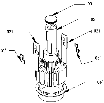
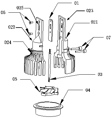
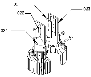
[0045] see figure 2 , a structural schematic diagram of a light-emitting lamp according to an embodiment of the present invention. The luminous lamp includes: a light source module 01 and a lamp body 02 . The lamp body 02 has ...


PUM


Abstract

The invention provides a light-emitting lamp. The design of the light-emitting lamp is matched with a light source module. When the light-emitting lamp is arranged, the light source module is arrangedin a region in a lamp body, the light-emitting angle and the radiation three-dimensional space angle are increased, the occurrence of a black area is avoided, and omni-directional effective light emitting is realized. In addition, the light source module and the lamp body are integrated, and mechanical fixation is added, so that the overall structure stability of the light-emitting lamp is improved, and the heat propagation path is greatly shortened.

Description

technical field [0001] The invention relates to the technical field of light emitting devices, in particular to a light source module and a light emitting lamp. Background technique [0002] Conventional LED light-emitting lamps, see figure 1 , including: lamp holder 04', lamp body 02' located on lamp holder 04', circuit board 021' located on both sides of lamp body 02', LED lamp bead 01' located on circuit board 021', and front of lamp body Cover 00. The lamp body front cover 00 should be on the top of the lamp body 02'. The LED lamp bead 01' is packaged by fixing the LED chip on the ceramic substrate with conductive glue. The LED lamp bead 01' is welded on the circuit board 021' by solder paste. The circuit board 021' is bonded and fixed on both sides of the lamp body 02' through thermal conductive silicone grease. The circuit board 021' is a copper-based or aluminum-based circuit board. [0003] The above-mentioned LED light-emitting lamps have problems in light dis...

Claims


Application Information

Patent Timeline
Patent Type & Authority Applications(China)
IPC IPC(8): F21K9/23F21V19/00F21V23/00F21V29/70F21V29/77F21V29/89F21Y115/10
Inventor 于正国
Owner 国瓷赛创电气(铜陵)有限公司
Why Eureka
Try Eureka