


Quick Research
Generate reliable direction feasibility study reports for your R&D in just a few steps.

Technical Q&A
Discover and master advanced knowledge NOW. Basics, ideas, possibilities, all at once.

Find Solutions
As an expert in R&D theories, this can generate solutions to your technical problems instantly.

Evaluate Feasibility
Analyze your overall solution with one click, know your potential R&D risks in advance.

Monitor Landscape
Get weekly tech updates, stay abreast of the latest tech innovations and key insights.
A kind of embedded column base joint equipped with section steel short beam and its construction method
A technology of embedded column feet and section steel, which is applied in the direction of columns, pillars, pier columns, etc., can solve the problems of large embedding depth, poor punching resistance and bending resistance, and complicated construction, so as to reduce project cost and The effect of small punching force and convenient construction
- Summary
- Abstract
- Description
- Claims
- Application Information
AI Technical Summary
Problems solved by technology
Method used
Image

Examples
specific Embodiment approach 1
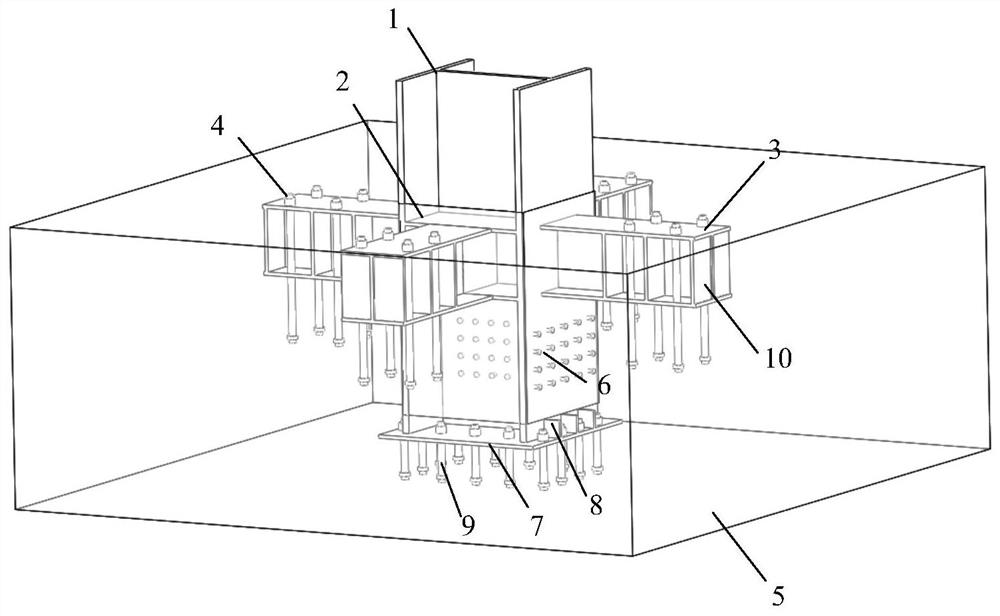
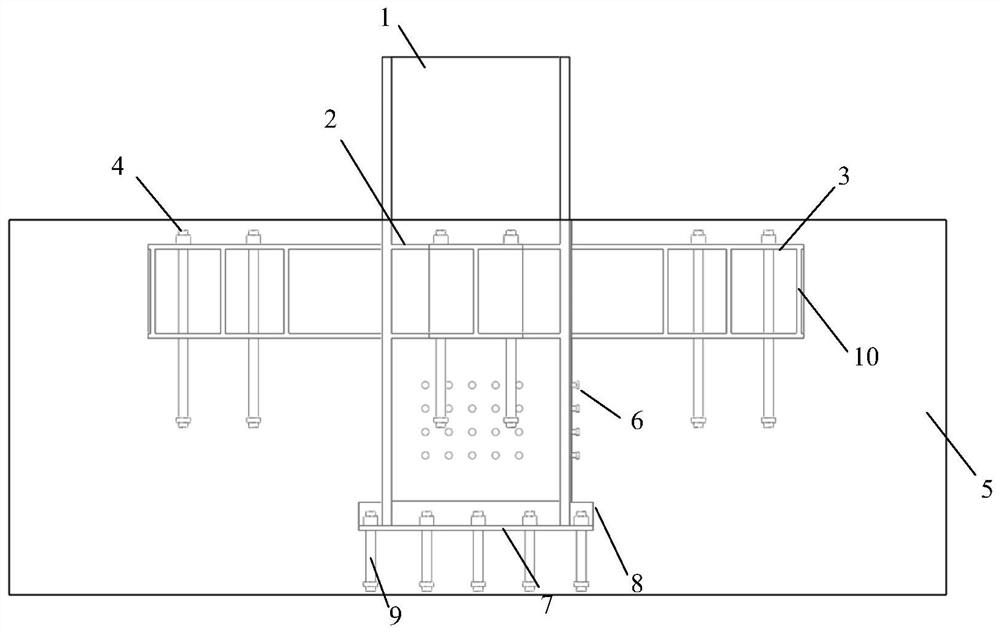
[0040] Specific implementation mode one: see Figure 1-3 This embodiment will be described. The embedded column foot node with section steel short beams described in this embodiment includes a column body 1, several section steel short beams 3, column bottom plates 7 and several anchor bolts; several section steel short beams are vertically connected around the column body 1 Beams 3, each of the short steel beams 3 is vertically penetrated with a number of anchor bolts, a column bottom plate 7 is installed under the column body 1, and the periphery of the column bottom plate 7 is vertically penetrated with a number of anchor bolts.
[0041] The section steel short beam 3 is an I-beam, box beam, welded steel beam or H-shaped steel beam, which can directly transmit the axial load of the column, increase the punching shear area of the concrete bottom beam, and significantly improve the punching shear resistance of the column base joints. At the same time, the short steel beam ...
specific Embodiment approach 2
[0055] Specific implementation mode two: see Figure 4-6 This embodiment will be described. In this embodiment, the column body 1 is a circular steel tube concrete column. The column bottom plate 7 is circular, and the diameter of the circle is larger than the diameter of the circular steel pipe concrete column.
[0056] The connecting plate 2 is fixed on the outer periphery of the circular steel tube concrete column as an integral structure, and the four short steel beams 3 are evenly connected to the outer surface of the circular steel tube concrete column through the connecting plate 2. The connecting plate 2 and the short steel beam 3's connection surface is on a plane. The section steel short beam 3 can be connected with the circular steel pipe concrete column through the connecting plate 2. Other structures and connections are the same as those in the first embodiment.
specific Embodiment approach 3
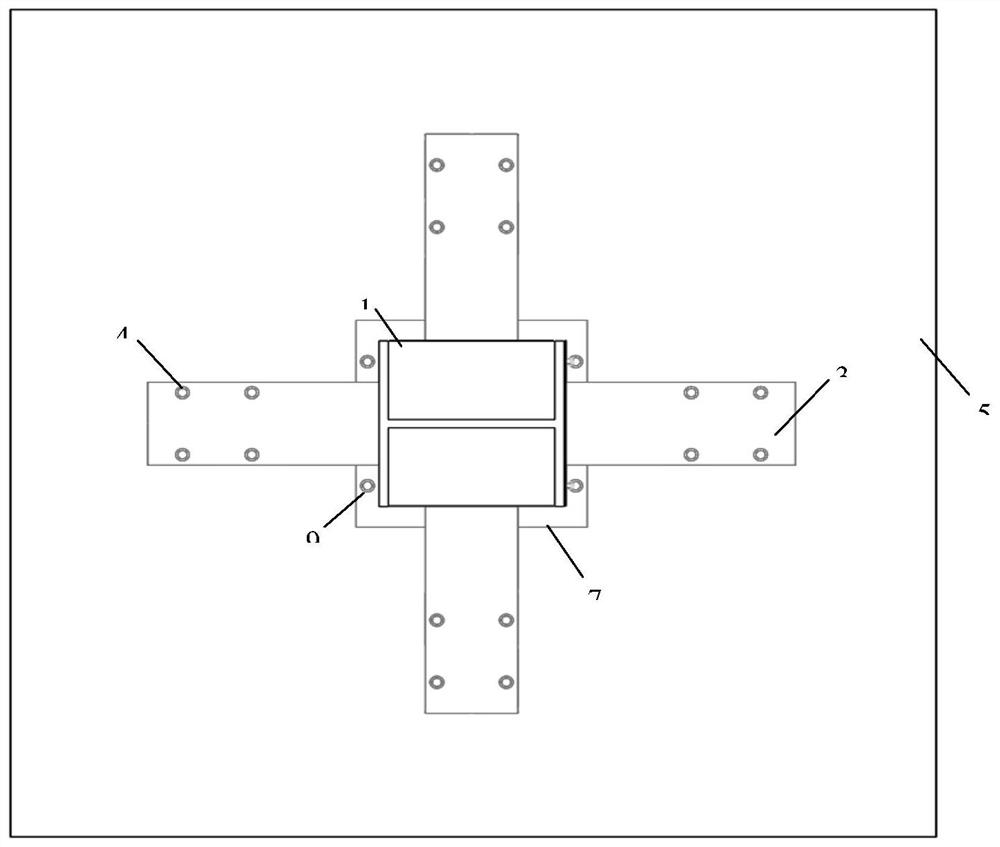
[0057] Specific implementation mode three: see Figure 7-9 This embodiment will be described. The column body 1 is a rectangular steel tube concrete column. The column bottom plate 7 is rectangular, and the side length of the rectangle is longer than the side length of the rectangular steel pipe concrete column.
[0058] The connecting plate 2 is fixed on the outer periphery of the rectangular steel tube concrete column as an integral structure, and the shape of the connecting plate 2 located on each side of the rectangular steel tube concrete column is "convex" shape, and the four short steel beams 3 and the connecting plate 2 The surrounding raised connections. Other structures and connections are the same as those in the first embodiment.
[0059] The concrete operation of the construction method of a kind of embedded type column base node that section steel short beam is housed according to the present invention is as follows:
[0060] Step 1: making the cylinder 1;
...
PUM
 Abstract
Description
Claims
Application Information
 - R&D Engineer
- R&D Manager
- IP Professional
- Industry Leading Data Capabilities
- Powerful AI technology
- Patent DNA Extraction
Browse by: Latest US Patents, China's latest patents, Technical Efficacy Thesaurus, Application Domain, Technology Topic, Popular Technical Reports.
© 2024 PatSnap. All rights reserved.Legal|Privacy policy|Modern Slavery Act Transparency Statement|Sitemap|About US| Contact US: help@patsnap.com