
Hank reel

A winch and rack technology, applied in the direction of conveying filamentous materials, thin material handling, transportation and packaging, etc., can solve the problems of reducing production efficiency, affecting production efficiency, long axial length, etc., to improve production efficiency, The effect of realizing the automation of threading and reducing the load of the rotating shaft

Pending Publication Date: 2019-06-07
张家港市塘桥镇鹿苑鑫森纺纱厂
View PDF1 Cites 8 Cited by
  • Summary
  • Abstract
  • Description
  • Claims
  • Application Information

AI Technical Summary

Problems solved by technology

[0002] The twisting machine is a machine that winds the package yarn on the rotary yarn frame to form a twist. The axial length of the rotary yarn frame of the traditional winding machine is long, and there are shaft seats at both ends, which are used to wind multiple packages at the same time. Twisting, this traditional twisting machine twists the twisted yarn after the yarn is started up (that is, the yarn head of the package yarn is fixed on the rotary yarn frame) and the winding is completed (the twisted yarn is twisted with a twisted wire) When divided into three strands), the entire rotary yarn frame does not work, which makes a large number of yarns that have been spun-up or skeined yarns that have been skeined idle, affecting production efficiency
[0003] In addition, in the process of skeining, when the yarn of a certain package is broken, it is necessary to stop the entire rotary yarn frame, connect the broken yarn, and start the machine again. This process causes a large number of packages to be idle. Greatly reduce production efficiency

Method used

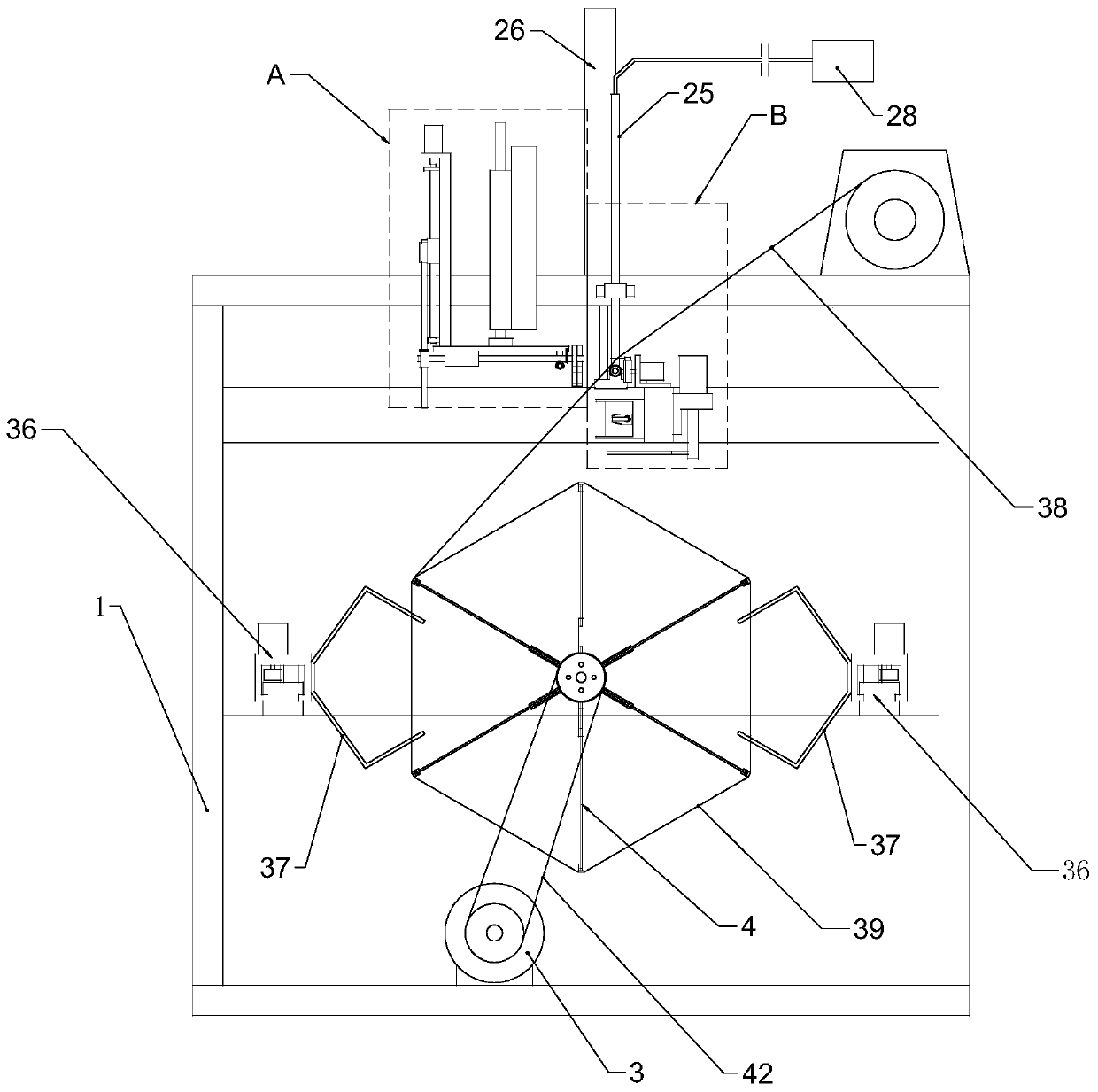
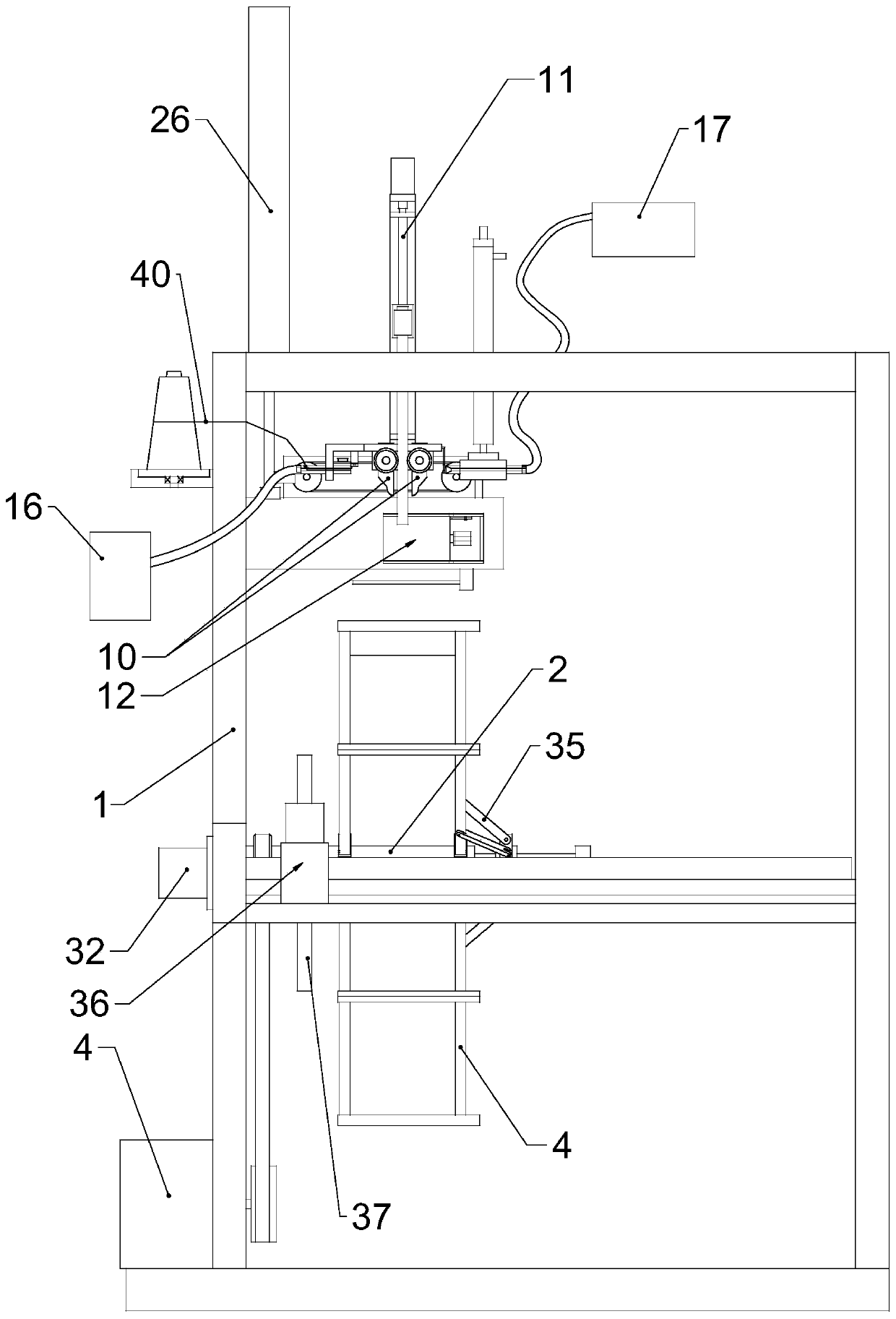
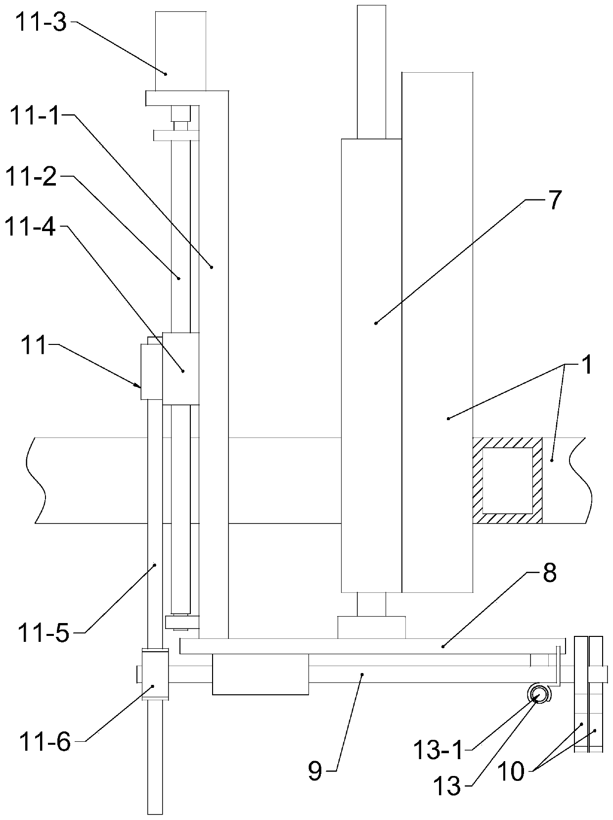

Image

  • Hank reel
  • Hank reel
  • Hank reel

Examples


Embodiment 1

[0049] like figure 1 and figure 2 As shown, the winching machine includes a frame 1, on which a horizontally arranged rotating shaft 2 and a main driving device 3 for driving the rotating shaft 2 are rotatably connected, and a rotary yarn frame 4 is fixedly connected on the rotating shaft 2, One end of the rotating shaft 2 is connected with the frame 1, and the other end is suspended, such as figure 1 and Figure 7 As shown, a yarn guide ring 5 is movably connected to the frame 1 above the rotary yarn frame 4, and the yarn guide ring 5 can move back and forth along the axial direction parallel to the rotating shaft 2. The frame 1 is also provided with a The yarn guide driving device 6 that the ring 5 moves back and forth.

[0050] combine Figure 10 As shown, the main driving device 3 is a servo motor or a stepping motor, which drives the rotating shaft 2 to rotate through the belt 42 , and the rotating shaft 2 is provided with a driven wheel 43 which is connected to the ...


PUM


Abstract

The invention relates to a hand reel. The hand reel comprises a rack, a horizontal rotating shaft and a main driving device for driving the rotating shaft to rotate are rotatably connected to the rack, a rotation yarn frame is fixedly connected to the rotating shaft, one end of the rotating shaft is connected with the rack, the other end of the rotating shaft hangs, a yarn guide ring is movably connected to the position, above the rotation yarn frame, of the rack, and can be parallel to the axial direction of the rotating shaft to move back and forth, a yarn guide driving device used for driving the yarn guide ring to move back and forth is arranged on the rack, the hand reel can greatly shorten the axial length of the rotation yarn frame, rotating shaft loads can be reduced, one end of the rotating shaft hangs to facilitate falling of hand yarn, the rotation yarn frame can wind one piece of hand yarn each time, synchronous starting or synchronous stop between pieces of hand yarn doesnot exist, the idle condition of the other yarn due to one-by-one making up or gradual hank tie can be avoided, and production efficiency is effectively improved.

Description

Technical field: [0001] The invention belongs to the technical field of textile machinery, and in particular relates to a shaking winch. Background technique: [0002] The twisting machine is a machine that winds the package yarn on the rotary yarn frame to form a twist. The axial length of the rotary yarn frame of the traditional winding machine is long, and there are shaft seats at both ends, which are used to wind multiple packages at the same time. Twisting, this traditional twisting machine twists the twisted yarn after the yarn is started up (that is, the yarn head of the package yarn is fixed on the rotary yarn frame) and the winding is completed (the twisted yarn is twisted with a twisted wire) When divided into three strands), the entire rotary yarn frame does not work, which makes a large number of bobbins that have finished spinning or skeined yarns that have been twisted to be in an idle state, affecting production efficiency. [0003] In addition, in the proces...

Claims


Application Information

Patent Timeline
IPC IPC(8): B65H54/22B65H54/28B65H69/04B65H57/12B65H65/00B65H51/005B65H54/58
Inventor 姚鑫森
Owner 张家港市塘桥镇鹿苑鑫森纺纱厂
Learn More