Long shaft part center adjustable quick clamping and machining device and operation method thereof
A technology for processing devices and shaft parts, which is applied in the field of adjustable center quick clamping processing devices for long shaft parts, can solve the problems of inability to realize dynamic clamping of parts, complex device structure, no processing function, etc., and achieves guaranteed processing. The effect of surface quality and dimensional accuracy, optimization of processing technology, and simplification of processing and installation procedures
- Summary
- Abstract
- Description
- Claims
- Application Information
AI Technical Summary
Problems solved by technology
Method used
Image


Examples
Embodiment 1
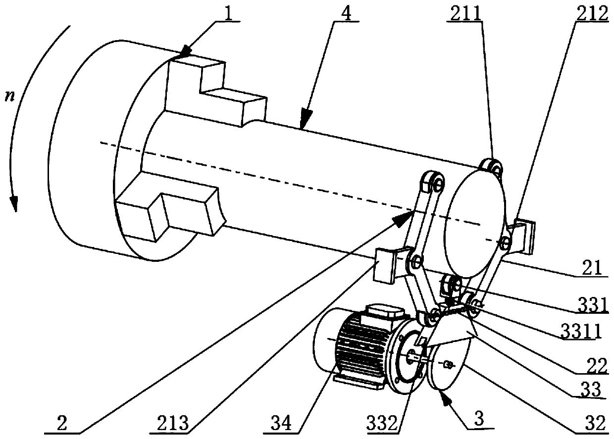
[0035]Based on the above structural basis, the shaft part 4 is clamped on the three-jaw chuck 1 and rotates at a high speed, the driving motor 34 is started, the driving cam 32 rotates, and the inclined-plane propulsion block 33 is pushed upward, and at the same time, the inclined surfaces on both sides of the inclined-plane propulsion block 33 push two The V-shaped rod 21 rotates around the fixed block 213 in the positive direction of the shaft part 4 to realize the clamping action, and the spring 22 connecting the two ends of the V-shaped rod 21 is stretched by force; the ends of the two V-shaped rods 21 are equipped with rollers 211, When clamping, the roller 211 rotates synchronously with the shaft part 4, thereby realizing dynamic clamping; at the same time, the screw feed tool 331 is installed with the roller 211, which forms a three-point support and fixation of the cylindrical part with the rollers at both ends of the V-shaped rod 21, and is advanced by the screw 3311 R...
Embodiment 2
[0037] Based on the above structural basis, the shaft part 4 is clamped on the three-jaw chuck 1 and rotates at a high speed, the driving motor 34 is started, the driving cam 32 rotates, and the inclined-plane propulsion block 33 is pushed upward, and at the same time, the inclined surfaces on both sides of the inclined-plane propulsion block 33 push two The V-shaped rod 21 rotates around the fixed block 213 in the positive direction of the shaft part 4 to realize the clamping action, and the spring 22 connecting the two ends of the V-shaped rod 21 is stretched by force; the ends of the two V-shaped rods 21 are equipped with rollers 211, When clamping, the roller 211 rotates synchronously with the shaft part 4, thereby realizing dynamic clamping; at the same time, the screw feed tool 331 is installed with a cutting tool, and the cutting feed of the tool is realized by advancing the screw rod 3311. After the clamping and breaking action is completed, the cam 211 is unclamped, an...
Embodiment 3
[0039] Based on the above structural basis, the shaft part 4 is clamped on the three-jaw chuck 1 and rotates at a high speed, the driving motor 34 is started, the driving cam 32 rotates, and the inclined-plane propulsion block 33 is pushed upward, and at the same time, the inclined surfaces on both sides of the inclined-plane propulsion block 33 push two The V-shaped rod 21 rotates around the fixed block 213 in the positive direction of the shaft part 4 to realize the clamping action, and the spring 22 connecting the two ends of the V-shaped rod 21 is stretched by force; the ends of the two V-shaped rods 21 are equipped with rollers 211, During clamping, the roller 211 rotates synchronously with the shaft part 4, thereby realizing dynamic clamping; at the same time, the screw feed tool 331 is equipped with a grinding wheel, and the screw 3311 is advanced to realize the feeding of the grinding tool. After the clamping and grinding action is completed, the cam 211 is released, an...
PUM
 Abstract
Description
Claims
Application Information
 - R&D
- Intellectual Property
- Life Sciences
- Materials
- Tech Scout
- Unparalleled Data Quality
- Higher Quality Content
- 60% Fewer Hallucinations
Browse by: Latest US Patents, China's latest patents, Technical Efficacy Thesaurus, Application Domain, Technology Topic, Popular Technical Reports.
© 2025 PatSnap. All rights reserved.Legal|Privacy policy|Modern Slavery Act Transparency Statement|Sitemap|About US| Contact US: help@patsnap.com