Atomizing nozzle structure of desuperheating valve

A technology of atomizing nozzle and desuperheating valve, applied in the direction of injection device, injection device, etc., can solve the problems of complicated installation of venturi, influence of desuperheating system pipeline, increase of pipeline difficulty, etc., so as to shorten production cycle and reduce production cost. , The effect of easy and quick assembly

Active Publication Date: 2019-06-04
CHONGQING CHUANYI CONTROL VALVE
View PDF8 Cites 3 Cited by
  • Summary
  • Abstract
  • Description
  • Claims
  • Application Information

AI Technical Summary

Problems solved by technology

However, the Venturi tube will affect the setting of the pipeline of the desuperheating system, which increases the difficulty of the pipeline design, and its price is also relatively expensive, which increases the cost and the installation of the Venturi tube is also complicated

Method used


Image

  • Atomizing nozzle structure of desuperheating valve
  • Atomizing nozzle structure of desuperheating valve
  • Atomizing nozzle structure of desuperheating valve

Examples


Embodiment Construction

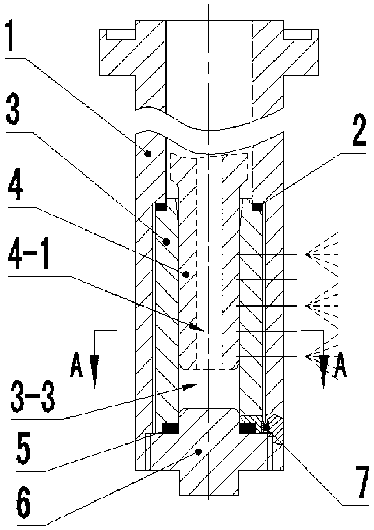
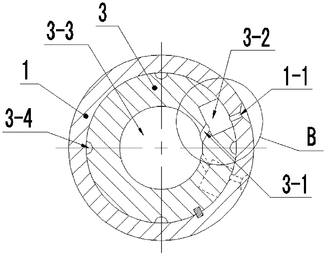
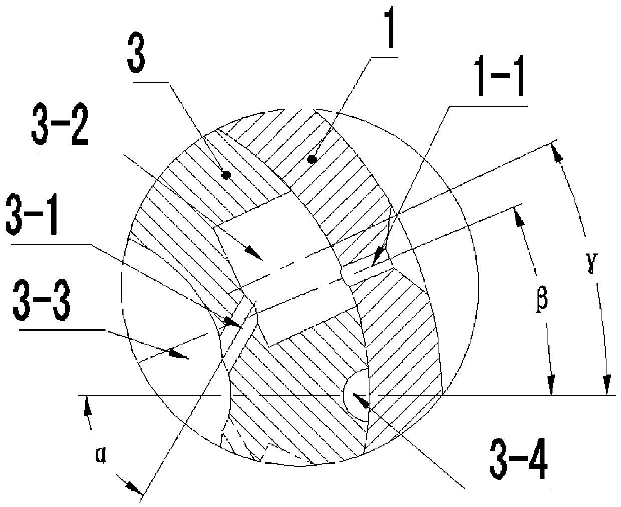
[0033] see Figure 1 to Figure 8, an atomizing nozzle structure of a temperature reducing valve, comprising a valve core 4 and a sleeve type atomizing nozzle, the axis of the valve core 4 is provided with a water hole 4-1, the valve core 4 and the valve of the temperature reducing valve Rod 8 is connected and fixed. The sleeve-type atomizing nozzle includes an outer sleeve 1 and an inner sleeve 3. The outer sleeve 1 is provided with a stepped hole 1-2 at the axis, and the inner sleeve 3 is assembled in the stepped hole 1-2 of the outer sleeve 1. The large-diameter hole of 2 has a clearance fit with the outer sleeve 1, and the clearance fit is a clearance fit with a high tolerance level. And the inner sleeve 3 is circumferentially positioned with the outer sleeve 1 through the key 7 , and the inner sleeve 3 and the outer sleeve 1 are correspondingly provided with key grooves for installing the key 7 . The upper end of the inner sleeve 3 is axially limited by the shoulder 1-3 ...


PUM


Abstract

The invention relates to an atomizing nozzle structure of a desuperheating valve. The atomizing nozzle structure of the desuperheating valve comprises a valve core and a sleeve-type atomizing nozzle,wherein a water passing hole is formed in the valve core; the sleeve-type atomizing nozzle comprises an outer sleeve and an inner sleeve, wherein a stepped hole is formed in an axial center of the outer sleeve, the inner sleeve is assembled in a large-diameter hole of the stepped hole of the outer sleeve and is in clearance fit with the outer sleeve and circumferentially positioned, and the upperend of the inner sleeve is axially limited by a hole shoulder of the stepped hole; a bottom plug is positioned at the lower end of the inner sleeve and is in threaded fit with the outer sleeve to limit the lower end of the inner sleeve; the valve core is in sliding fit with a shaft hole of the inner sleeve; a plurality of flow passage holes are axially formed in one side of the inner sleeve hole wall; a plurality of vortex cavities corresponding to the flow passage holes separately are formed in the inner sleeve outer wall, and the diameter of the vortex cavities is larger than that of the flow passage holes; the vortex cavities communicate with the shaft hole of the inner sleeve through the flow passage holes, and the axial direction of the flow passage holes and the axial direction of the vortex cavities are in an oblique state; a plurality of atomizing spray holes are axially formed in one side of the outer sleeve hole wall, and the atomizing spray holes communicate with the corresponding vortex cavities separately; and the diameter of the atomizing spray holes is smaller than that of the flow passage holes, and nozzles of the atomizing spray holes are in trumpet shapes.

Description

technical field [0001] The invention relates to the field of steam temperature reduction valves, in particular to an atomizing nozzle structure of the temperature reduction valve. Background technique [0002] The temperature and pressure reducer is a kind of equipment commonly used in the production of energy such as electric power and chemical industry. It is mainly used to reduce the temperature and pressure of the high-temperature and high-pressure steam generated by the gas supply boiler, so that the steam can reach specific parameters. Meet the requirements of production. Among them, the steam desuperheating process is completed through the desuperheating valve of the desuperheating and pressure reducing valve. The desuperheating valve mixes the desuperheating water into the steam, so that the desuperheating water evaporates and absorbs heat to realize the cooling of the high temperature steam. At present, the nozzles of desuperheating valves for spraying desuperheati...

Claims


Application Information

Patent Timeline
Patent Type & Authority Applications(China)
IPC IPC(8): B05B1/20B05B1/34B05B13/02
Inventor 郝娇山谌传江刘柏圻杨恒虎张奋强
Owner CHONGQING CHUANYI CONTROL VALVE
Why Eureka
Try Eureka