
Tea leaf machine equipment with spiral air supply device

An air supply device and a screw-type technology, applied in the field of tea machine equipment, can solve the problems of affecting the quality of tea leaves, not being able to bake the tea leaves evenly, and the quality of the tea leaves being degraded.

Inactive Publication Date: 2019-05-21
HUBEI WUFENG HUASHENG TEA MACHINERY
View PDF0 Cites 2 Cited by
  • Summary
  • Abstract
  • Description
  • Claims
  • Application Information

AI Technical Summary

Problems solved by technology

It has the following problems: the traditional pot is reciprocating and linearly moving under the action of the transmission mechanism of the equipment itself, so that the tea leaves in the pot are turned over, dried and dehumidified
However, the linear reciprocating motion can generally only cause the tea leaves in the tank to tumbling left and right, but cannot form a full range of up and down, left and right, and tossing that imitates manual rolling, resulting in a decline in the quality of the tea leaves and affecting the quality of the tea leaves.
In addition, the traditional heating and heat delivery method uses warm air, which makes the temperature of each part in the tank different, so that the tea leaves cannot be evenly baked, resulting in uneven quality of tea in the tank

Method used


Image

  • Tea leaf machine equipment with spiral air supply device

Examples


Embodiment Construction

[0013] The present invention will be described in detail below in conjunction with the accompanying drawings and specific embodiments, wherein the schematic embodiments and descriptions are only used to explain the present invention, but are not intended to limit the present invention.

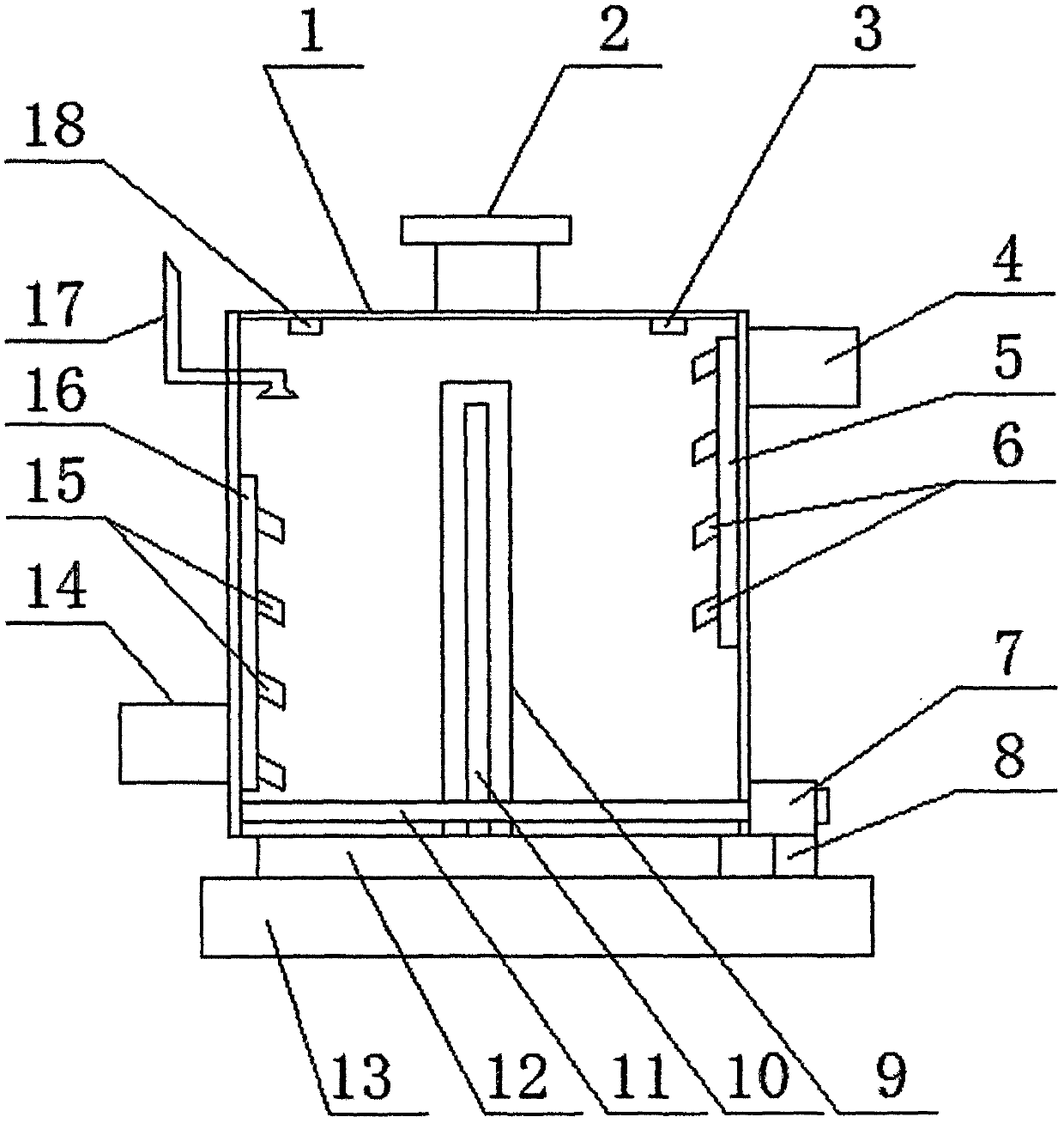
[0014] Such as figure 1 As shown, the tea machine equipment with a spiral air supply device described in this specific embodiment includes a tea machine main body, and the tea machine main body includes a workbench 13 on which a heating device 12 is arranged. The heating device 12 is provided with a pot 1, and the middle part of the upper surface of the pot 1 is provided with a feed port 2; the pot 1 is provided with an air supply assembly; The lower part of the side is provided with a vertical air duct A16, and the right side of the vertical air duct A16 is provided with an oblique air outlet A15. A14 is connected; the upper part of the right side of the tank 1 is provided with a vertical ai...


PUM


Abstract

The invention relates to the technical field of tea leaf machine equipment and particularly relates to tea leaf machine equipment with a spiral air supply device. The tea leaf machine equipment comprises a tea leaf machine main body; the tea leaf machine main body comprises a workbench; a heating device is arranged on the workbench; a tank pot is arranged on the heating device; a feeding port is formed in the middle part of the upper surface of the tank pot; an air supply assembly is arranged on the tank pot; the air supply assembly comprises a vertical air pipe A which is arranged at the lower part of the left side surface of the interior of the tank pot; oblique air outlet pipe orifices A are foremd in the right side surface of the vertical air pipe A; the vertical air pipe A is connected with a fan A which is arranged at the lower part of the left side surface of the tank pot; a vertical air pipe B is arranged at the upper part of the right side surface of the interior of the tank pot; oblique air outlet pipe orifices B are formed in the right side surface of the vertical air pipe B; and the vertical air pipe B is connected with a fan B which is arranged at the upper part of theright side surface of the tank pot. The tea leaf machine equipment has the advantages that the structure is simple, the cost is low, tea leaves can be dried uniformly, the working efficiency is high,and the quality of products is improved.

Description

technical field [0001] The invention relates to the technical field of tea machine equipment, in particular to a tea machine equipment with a spiral air supply device. Background technique [0002] In the traditional tea machine, its structure adopts a tank and an air supply device arranged on the tank, and the air supply device is generally composed of an air duct and a fan. It has the following problems: the traditional tank makes reciprocating linear motion under the action of the transmission mechanism of the equipment itself, so that the tea leaves in the tank are tossed and dried to remove moisture. However, the linear reciprocating motion generally can only cause the tea leaves in the tank to tumbling left and right, but cannot form a full range of up, down, left, and right and tossing that imitates manual twisting, resulting in a decline in the quality of the tea leaves and affecting the quality of the tea leaves. In addition, the traditional heating and heat delive...

Claims


Application Information

Patent Timeline
Patent Type & Authority Applications(China)
IPC IPC(8): F26B11/12F26B21/00F26B23/06F26B25/00F26B25/04F26B25/22A23F3/06
Inventor 史江峰袁中华裴文武
Owner HUBEI WUFENG HUASHENG TEA MACHINERY
Learn More