
A kind of steel truss construction method

A steel truss and construction method technology, which is applied in the processing of building materials, construction, building components, etc., can solve the problem of large gaps at the junction of steel truss slabs and steel columns, not meeting the rapidity of steel structure construction, and difficult manual operation accuracy. Control and other issues, to achieve the effect of reducing the workload on site, improving the phenomenon of slurry leakage, and reducing labor consumption

Active Publication Date: 2020-11-24
CHINA RAILWAY CONSTR GRP BEIJING ENG CO LTD +1
View PDF6 Cites 0 Cited by
  • Summary
  • Abstract
  • Description
  • Claims
  • Application Information

AI Technical Summary

Problems solved by technology

[0002] As the country vigorously advocates prefabricated buildings, steel structure buildings are increasing day by day. Reinforced truss panels are widely used in steel structure construction projects. The steel plate is welded into one composite structural system, all of which are processed and manufactured in the factory, and the components can be installed immediately when they are transported to the construction site. The steel truss plate is a standard plate processed by the factory. Plasma cutting machine is used for on-site manual cutting, and the accuracy of manual operation is difficult to control, resulting in a large gap at the junction of the steel truss slab and the steel column. Before subsequent concrete pouring, sealing treatment is required to prevent grout leakage. Many, manual sealing is time-consuming and labor-intensive, and the effect is not obvious. The position of the traditional studs often collides with the steel bars during the welding process. It is necessary to adjust the positions of the studs to avoid the steel bars on site, which is not conducive to workers' operation. The traditional cantilever plate support All adopt steel pipe frame or bowl frame, which is time-consuming and labor-intensive, and does not meet the rapidity of steel structure construction

Method used


Image

  • A kind of steel truss construction method

Examples


Embodiment

[0028] The concrete realization of this embodiment is described in detail below:

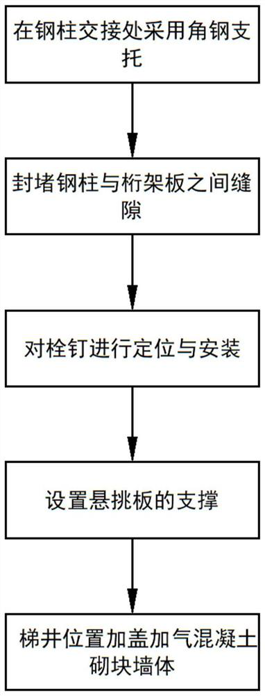
[0029] (1) Install steel truss slabs, and use 50×5 angle steel brackets at the junction of steel columns, and the brackets and steel beams are connected by welding.

[0030] During the steel column processing and manufacturing process in the factory, the steel plate support is welded to the steel column according to the floor elevation, so that the steel truss plate support can be completed at one time during the component processing process, and the on-site installation welding angle steel support process is cancelled.

[0031] (2) After the rib truss plate is installed, cut it according to the actual size of the site. After cutting, the gap between the steel column and the truss plate is cut into an L shape with a 0.75mm thick hot-dip galvanized steel plate for sealing

[0032] (3) Studs are used The number of rows is determined by the design according to the beam width. Adjust and optimize ...


PUM


Abstract

The invention discloses a steel bar truss construction method. The method realizes steel bar truss plate support at a time in a component machining process, cancels a process of installing and weldingangle steel supports on site, and reduces field workload; the angle steel support is arranged, so that after the steel bar truss plate is cut, the deviation between the steel bar truss plate and a steel column gap is controlled within 50mm to meet requirements; a grout leakage phenomenon is greatly improved after the concrete pouring is finished; installation time of studs is shortened through anadjusted spacing of the studs; meanwhile, additional studs under the condition of the original spacing are avoided, the usage amount of the studs is saved, supporting operation of a cantilever plateis simple, consumed manpower is little, the dismantling problem does not to be considered, later decoration is hidden in a decorated ceiling, and the service cycle of a scaffold is shortened.

Description

technical field [0001] The invention relates to a truss construction method, in particular to a steel bar truss construction method, and belongs to the technical field of building construction. Background technique [0002] As the country vigorously advocates prefabricated buildings, steel structure buildings are increasing day by day. Reinforced truss panels are widely used in steel structure construction projects. The steel plate is welded into one composite structural system, all of which are processed and manufactured in the factory, and the components can be installed immediately when they are transported to the construction site. The steel truss plate is a standard plate processed by the factory. Plasma cutting machine is used for on-site manual cutting, and the accuracy of manual operation is difficult to control, resulting in a large gap at the junction of the steel truss slab and the steel column. Before subsequent concrete pouring, sealing treatment is required to ...

Claims


Application Information

Patent Timeline
Patent Type & Authority Patents(China)
IPC IPC(8): E04B5/40E04G21/14
Inventor 董正申高岳常世海
Owner CHINA RAILWAY CONSTR GRP BEIJING ENG CO LTD
Learn More