High-performance temperature equalization device

A high-performance, liquid-absorbing core technology, which is applied in the direction of cooling/ventilation/heating transformation, can solve the problems of restricting product quality, performance improvement, unfavorable wide use of temperature equalization devices, and decline in welding quality, so as to expand the scope of use and areas, efficient and stable performance indicators, and the effect of improving utilization

Pending Publication Date: 2019-05-17
XINXIANG TEMEITE HEAT TRASFER EQUIP CO LTD
View PDF0 Cites 1 Cited by
  • Summary
  • Abstract
  • Description
  • Claims
  • Application Information

AI Technical Summary

Problems solved by technology

The use of vacuum brazing to manufacture uniform temperature devices in the field has the following four problems that seriously restrict the improvement of product quality and performance
First, the temperature equalizing device manufactured by the vacuum brazing process in the field has only one layer of liquid-absorbing core, and vacuum brazing is not performed between the liquid-absorbing core and the aluminum alloy, and the vacuum brazing solder is only laid on the opposite side of the liquid-absorbing core , the purpose of this design is mainly to separate the liquid-absorbing core from the brazing material, because the brazing material will melt into a liquid state during vacuum brazing, and will often be absorbed by the liquid-absorbing core along the supporting column or the surrounding walls, resulting in brazing Insufficient solder on the welding surface reduces the welding quality, and the inner cavity of the product has high pressure when it is working, which often causes the brazing seam to tear and cause the upper and lower surfaces of the product to bulge, and also causes the pores of the liquid-absorbing core to be filled with solder and lose the capillary force. Function, resulting in product function reduction or failure
Second, in order to separate the liquid-absorbing core from the brazing material, only one surface of the upper and lower sides of the inner chamber of the temperature uniform device can be provided with a liquid-absorbing core, and the other surface is the surface on which the brazing material is laid. When the temperature uniform device is working, it can only be The liquid-absorbing core on one side provides the capillary force of the working medium, and the other side will retain a large amount of liquid working medium that cannot return to the heat source to absorb heat and vaporize to form a cycle, resulting in low performance of the temperature equalizing device, which seriously restricts the improvement of product performance
Third, temperature equalizing devices are widely used in aviation, aerospace, electronics and other fields. Usually, the temperature equalizing device is required to be thinner and lighter in weight. Setting brazing surfaces in the upper and lower cover plates will often increase the thickness of the cover plate and the bottom plate , leading to an increase in the overall thickness of the temperature equalizing device, and a substantial increase in weight, which does not take advantage of the widespread use of the temperature equalizing device
Fourth, in the actual use environment, the heat source is usually only on the top or bottom, and the working medium of the liquid-absorbing core close to the heat source surface absorbs heat and vaporizes strongly, and the liquid working medium on the opposite side flows back to the bottom of the heat source only by supporting columns and The walls around the inner cavity have few return paths and low return efficiency, which greatly reduces the temperature uniformity of the product

Method used


Image

  • High-performance temperature equalization device
  • High-performance temperature equalization device
  • High-performance temperature equalization device

Examples


Embodiment Construction

[0028] The present invention will be described in detail below in conjunction with the accompanying drawings. It should be noted that the orientation terms such as left, middle, right, up, and down in the examples of the present invention are only relative concepts or refer to the normal use state of the product, and should not be considered as restrictive .

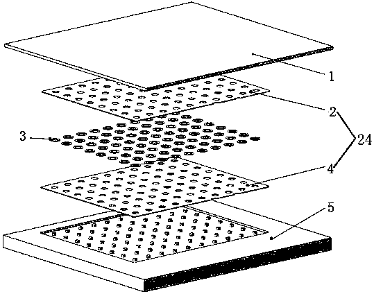
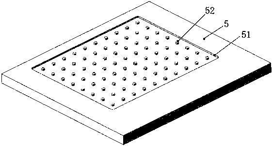
[0029] A high-performance temperature equalization device, such as figure 1 , figure 2 , Figure 7 and Figure 8 As shown, it includes a base plate 5, a liquid-absorbing core 24 and a cover plate 1. The cover plate 1 is fixed on the base plate 5, and a square cavity 51 is provided between the cover plate 1 and the base plate 5. The liquid-absorbing core 24 is located in the cavity 51, and a supporting column 52 is distributed in the cavity 51, and the supporting column 52 is arranged through the liquid-absorbing core 24. The two ends of the supporting column 52 It is fixedly connected with the bottom plate 5 and th...


PUM


Abstract

A high-performance temperature equalization device comprises a bottom plate, a liquid absorption core and a cover plate, wherein the cover plate is fixedly arranged on the bottom plate, a cuboid cavity is formed between the cover plate and the bottom plate, the liquid absorption core is arranged in the cavity, support posts are arranged in the cavity and are arranged on the liquid absorption corein a penetrating way, two ends of the support posts are fixedly connected with the bottom plate and the cover plate, a fixed sleeve fixedly sleeves each support post, an end surface of one end of thefixed sleeve is attached onto the cover plate and is fixedly connected with the cover plate, grooves are formed in an inner wall of the fixed sleeve and the cover plate, the support post is fixedly connected with a side wall and a bottom surface of the groove by vacuum soldering, the bottom plate and the cover plate both are attached onto the liquid absorption core, the groove in the cover plate is assembled with the support post on the bottom plate so that a soldering position is thoroughly separated from the liquid absorption core, and the liquid absorption core is prevented from losing capillary force function; and meanwhile, the welding quality of vacuum soldering is improved to a great extent, a high-efficiency and stable performance index of the temperature equalization device is provided, the upper-layer liquid absorption core and the cover plate can be more closely attached by a diversion ring, and the heat conduction capability and the heat transfer capability of the device are improved.

Description

technical field [0001] The invention relates to a heat dissipation device, in particular to a high-performance temperature uniform device. Background technique [0002] With the development of science and technology, electronic equipment is developing rapidly in the direction of high heat flux density and micro volume, and the heat source of electronic equipment is usually a point heat source. The failure to transfer the heat in time will lead to local overheating of electronic equipment, resulting in damage to electronic equipment . [0003] Vapor panels have the characteristics of light weight, high thermal conductivity, excellent temperature uniformity and no need for external power. The vapor chamber is a flat structure, and various bosses can be set according to the needs of the heat source, which can directly contact with one or more electronic devices at the same time. When the electronic equipment heats up, the vapor chamber can quickly transfer the heat almost iso...

Claims


Application Information

Patent Timeline
IPC IPC(8): H05K7/20
Inventor 张瑞梁光飞青振江
Owner XINXIANG TEMEITE HEAT TRASFER EQUIP CO LTD
Why Eureka
Try Eureka