Mask forming method and mask

A reticle and test mask technology, which is applied in the reticle formation method and the reticle field, can solve problems such as cumbersome operations, and achieve the effects of simplifying operations, reducing lithography costs, and improving lithography efficiency.

Active Publication Date: 2021-11-05
YANGTZE MEMORY TECH CO LTD
View PDF8 Cites 0 Cited by
  • Summary
  • Abstract
  • Description
  • Claims
  • Application Information

AI Technical Summary

Problems solved by technology

[0006] The invention provides a method for forming a reticle and a reticle, which are used to solve the problem of cumbersome operations when forming a photoresist with a specific thickness on the surface of a wafer in the prior art, so as to improve the production efficiency of semiconductors and reduce the production cost of semiconductors

Method used


Image

  • Mask forming method and mask
  • Mask forming method and mask
  • Mask forming method and mask

Examples


Embodiment Construction

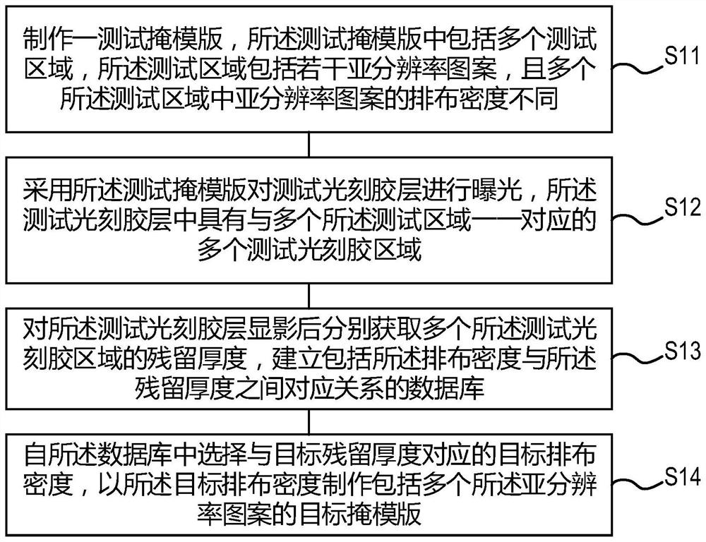
[0048] The method for forming the reticle provided by the present invention and the specific implementation of the reticle will be described in detail below with reference to the accompanying drawings.

[0049] In the photolithography process, it is often necessary to adjust the thickness of the photoresist in different regions of the wafer surface, so as to control the ion implantation depth and etching depth in different regions of the wafer surface. At present, in order to form a photoresist layer with a specific thickness on different regions of the wafer surface, the following two methods are mainly used: one is to expose and develop the photoresist layer, and through multiple exposure and development processes, the Forming a photoresist layer with a specific thickness on the surface of the wafer; the other is to change the physical and / or chemical properties of the light-absorbing material in a specific area of ​​the reticle, thereby changing the light transmittance of th...


PUM

PropertyMeasurementUnit
transmittivityaaaaaaaaaa

Abstract

The invention relates to the technical field of semiconductor manufacturing, in particular to a method for forming a reticle, a photolithography method and a reticle. The method for forming a reticle includes the following steps: making a test reticle including a plurality of test areas, the test area includes several sub-resolution patterns, and the sub-resolution patterns in each test area have different arrangement densities; using the test reticle to pair The test photoresist layer is exposed; after developing the test photoresist layer, a database including the corresponding relationship between the arrangement density and the residual thickness is established; the target arrangement density corresponding to the target residual thickness is selected from the database, and the Fabricate a target reticle including a plurality of sub-resolution patterns according to the target arrangement density. The invention greatly simplifies the operation of forming a photoresist layer with a specific thickness on the surface of the wafer, reduces the cost of photolithography, and improves the efficiency of photolithography.

Description

technical field [0001] The invention relates to the technical field of semiconductor manufacturing, in particular to a method for forming a reticle and the reticle. Background technique [0002] With the development of planar flash memory, the production process of semiconductors has made great progress. However, in recent years, the development of planar flash memory has encountered various challenges: physical limits, existing development technology limits, and storage electron density limits. In this context, in order to solve the difficulties encountered in planar flash memory and pursue lower production costs per unit storage unit, various three-dimensional (3D) flash memory structures have emerged, such as 3DNOR (3D or not) flash memory and 3D NAND (3D NAND) flash memory. [0003] Among them, 3D NAND memory takes its small size and large capacity as the starting point, and adopts the high integration of storage units stacked in three-dimensional mode as a design conc...

Claims


Application Information

Patent Timeline
Patent Type & Authority Patents(China)
IPC IPC(8): G03F7/20G03F1/50
Inventor 姚军曹清晨刘峻胡小龙高峰
Owner YANGTZE MEMORY TECH CO LTD
Why Eureka
Try Eureka