Grease lubricated harmonic deceleration drive device and lubricating method thereof
A harmonic deceleration and driving device technology, which is applied in the direction of transmission, gear transmission, engine lubrication, etc., can solve the problems of lubricant loss, lubricant stability, etc., and achieve the effect of improving service life and preventing volatilization and loss
Inactive Publication Date: 2014-05-14
SHANGHAI AEROSPACE SYST ENG INST
View PDF0 Cites 1 Cited by
- Summary
- Abstract
- Description
- Claims
- Application Information
AI Technical Summary
Problems solved by technology
The problem that the present invention is required to solve is to overcome the deficiencies in the above-mentioned prior art, and solve the problem of lubricant loss and lubricant stability.
Method used
View moreImage
Smart ImageViewing Examples

Examples
Embodiment Construction
Login to View More PUM
 Abstract
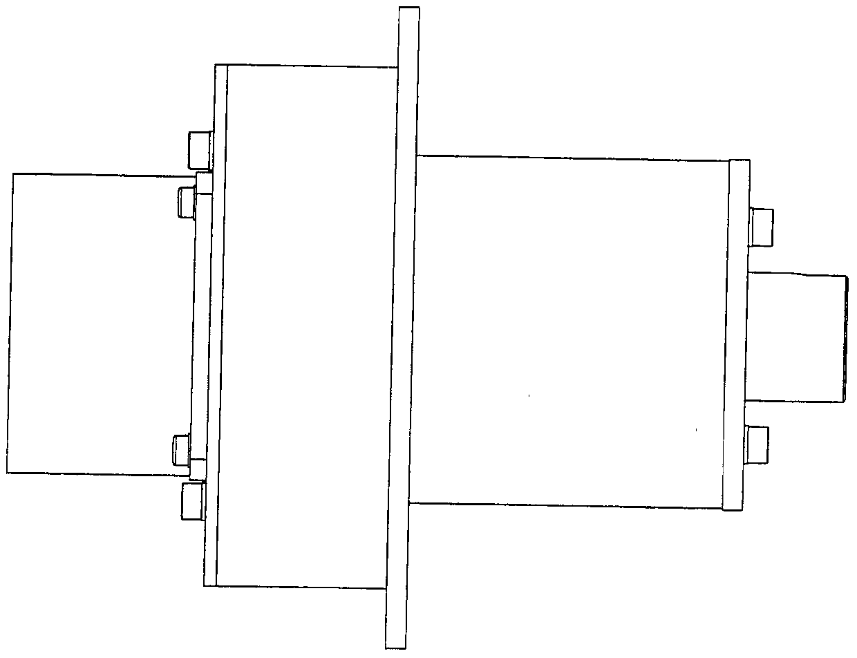
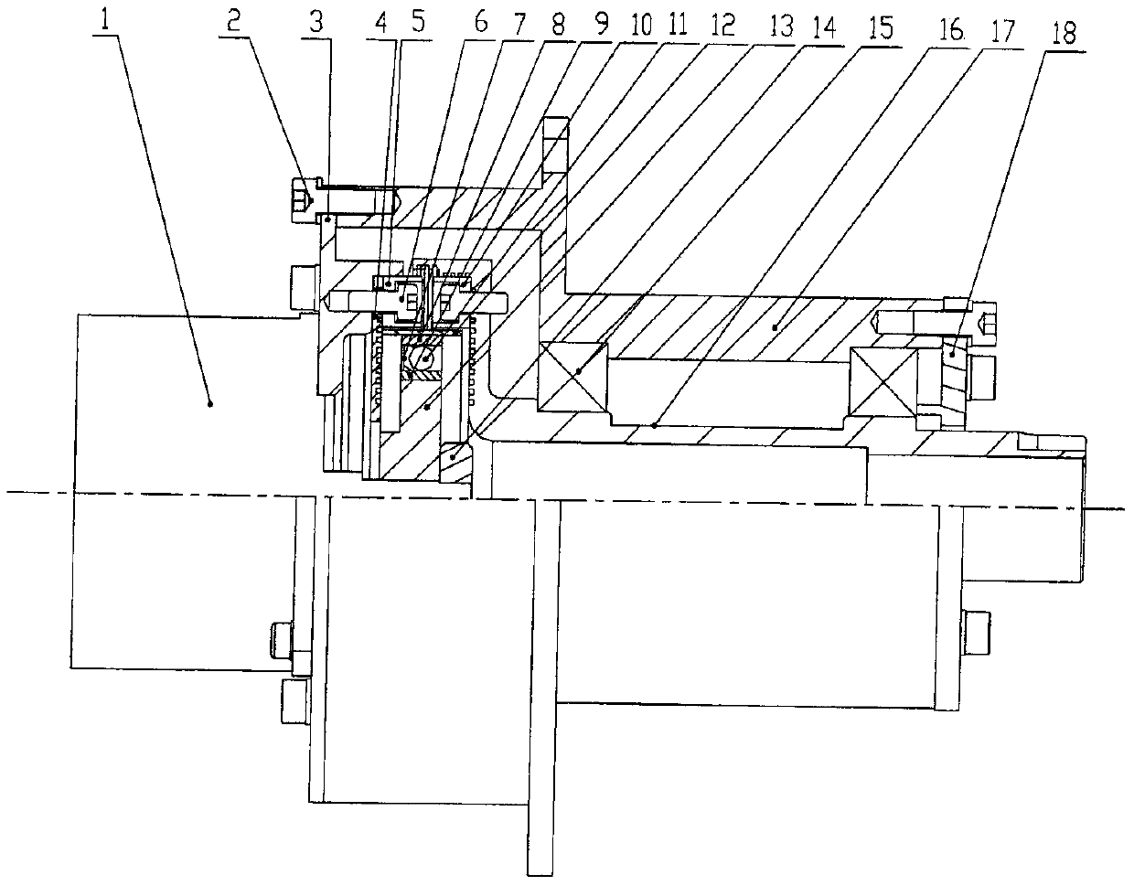
The invention discloses a grease-lubricated harmonic deceleration drive device and a lubricating method thereof. The motor output shaft drives a wave generator to rotate, and the teeth of the flexible wheel mesh with the teeth of the output rigid wheel, so that the output rigid wheel rotates and the output rigid wheel rotates. The wheel is connected with the drive shaft, and drives the drive shaft to rotate after deceleration, and provides radial and axial support to the drive shaft through the bearing. The drive shaft is supported by the bearing and rotates freely around the center line of rotation. The input rigid wheel and the output are on the gear meshing surface. Perfluoropolyether grease (601EF) is applied to the meshing part of the rigid wheel and the flexible gear teeth for vacuum grease lubricating film treatment, and the flexible bearing cage is treated with vacuum oil immersion; the oil immersion rate is controlled at 15% of the weight of the cage. 20%; creates a tortuous path between the drive shaft and stop lubricating surface and the outer surface. The use of the lubricant of the invention is not easy to volatilize and run off, greatly reduces the loss of the lubricant under the condition of low air pressure, and effectively increases the service life of the lubricant.
Description
technical field The invention relates to the technical field of space vehicle motion mechanisms, in particular to a grease lubricated harmonic deceleration drive device and a lubricating method thereof. Background technique The lubrication of the space mechanism is an important way to ensure the reliability and normal operation of the mechanism. It is used to ensure that the kinematic pair has good and stable friction characteristics during the movement. Usually, three types of methods are used: solid lubrication, oil lubrication and grease lubrication. The existing deceleration driving device usually adopts the solid lubrication method, which has the characteristics of wide temperature range and no volatilization. However, for the deceleration drive device using solid lubrication, it has the following disadvantages: a. It can only be used in low-speed, light-load motion conditions; b. The operating life is short, at 10 6 It is only suitable for occasions with low preci...
Claims
Login to View More Application Information
Patent Timeline
 IPC IPC(8): F16H1/28F16N17/06
Inventor 金典顺杨金平钱志源李瑞祥王治易
Owner SHANGHAI AEROSPACE SYST ENG INST
Features
- R&D
- Intellectual Property
- Life Sciences
- Materials
- Tech Scout
- Unparalleled Data Quality
- Higher Quality Content
- 60% Fewer Hallucinations
Learn More Browse by: Latest US Patents, China's latest patents, Technical Efficacy Thesaurus, Application Domain, Technology Topic, Popular Technical Reports.
© 2025 PatSnap. All rights reserved.Legal|Privacy policy|Modern Slavery Act Transparency Statement|Sitemap|About US| Contact US: help@patsnap.com